The test rig
Once I received the first professionally assembled boards, there was one last thing to do to confirm the design behaves just as expected: testing it!
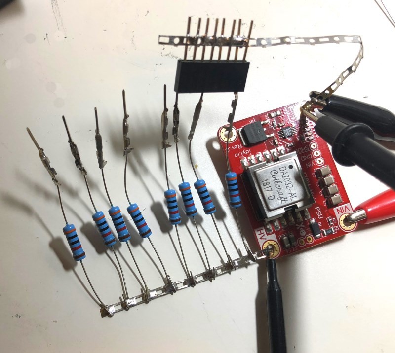
I measured the efficiency of the power supply using a rig made out of a female header and a bunch of 30k resistors. That way I can measure loads at roughly 5mA intervals (170V / 30K = 5.7mA per resistor). The good thing about working with high voltage/small current is that you can get away with really small wires. The big chunk of metal used here is more than capable of handling that load.

In addition to that, measurements were made using 3 different source voltages: 5V, 9V and 12V. It would technically be possibly to power the supply with 4.7V lipo but that would require extensive battery protection mechanisms. For that particular reason I decided to not include this test as it might encourage unsafe operations.
Test results!
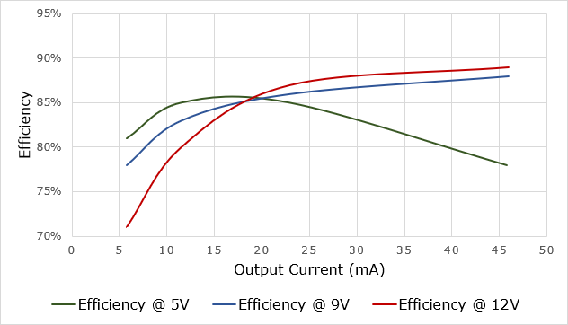
Without further ado, here are the results:

At 5V the power supply is pretty impressive. Having over 80% efficiency on this ~34 boost ratio is an amazing result! Past 20mA it quickly drops though, showing the limits of the design at such low voltage. That being said, this makes a nixie clock driven by a single 5V wall wart completely possible! Very exciting!
9 and 12V are showing similar curves, and the power supply can output well over 40mA@170V using these. On very low current (~5mA) the 12V input shows a lackluster 71% efficiency but it rapidly increases to 85%+ efficiency as hte load increases.
I pushed the power supply all the way past 50mA but past that it’s simply just an absurd amount of current to power tubes. It simply means the power supply operates well within its capabilities and will be extremely reliable. Those tests are a complete pass!
 Tony
Tony
Discussions
Become a Hackaday.io Member
Create an account to leave a comment. Already have an account? Log In.