 Poyu Chen
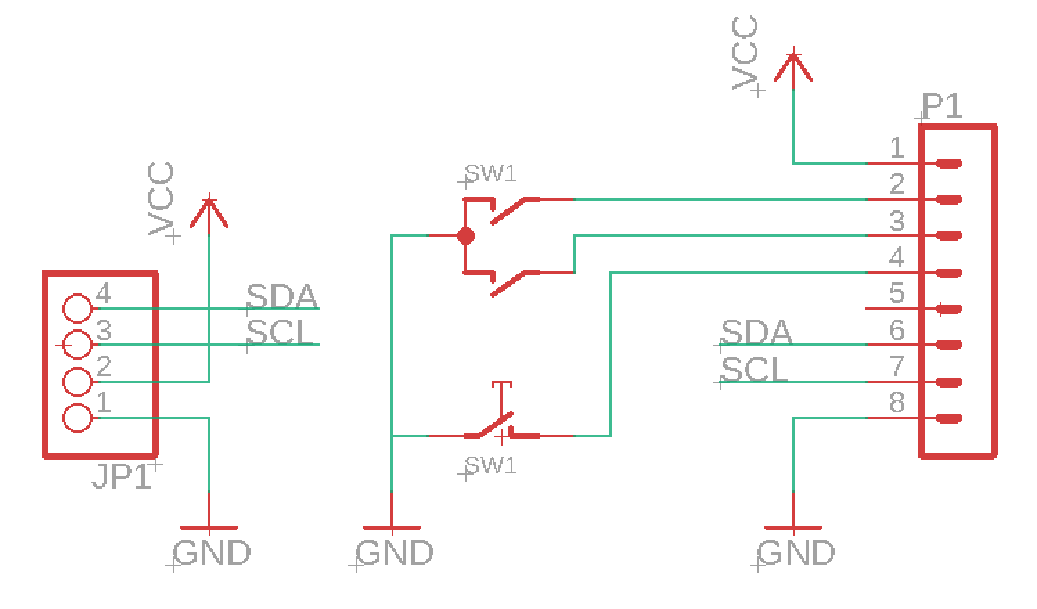
It's time to finalize the hardware to an actual board. I've just finished designing the OLED and encoder board. I decided to use a 8pin JST connector to connect the board to wire.
One part I haven't figured out is how to connect this to the Pi's pins. Given that I just ordered around 300 JST connecters from LCSC, I think I'll design another board that connect's to Pi's header pins which will output 2 connecters, 1) a 2pin 5v power and 2) a 8pin OLED connector.
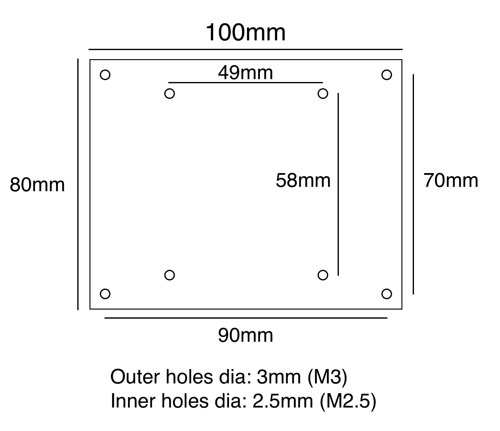
To mount the board, I have 4 holes on each corner with M2 screw size. As to mounting the Pi to my rack, since I'm using Intellijel's 104HP case, I can use the same rail it uses to mount the power board. The two rails are exactly 7cm apart, and it takes M3 nuts, so I just need to slide it in and screw it on. There will be a "carrier" board to carry the Pi and then that get's screwed to the case. (make sense??)
Another thing I need to design, is the panel that'll go on the rack. Perhaps I'll design 2 types, one for the Intellijel 1U format the other for the other 1U format. This will also hold a 2 port USB extension cable that'll go to the Pi.
Anyway, here are some pics

Discussions
Become a Hackaday.io Member
Create an account to leave a comment. Already have an account? Log In.