Eric Hertz
-
RAMdom updates
11/27/2018 at 19:25 • 3 commentsBought a string of "holiday festive lights" from the dollar-store. $1, 20 bulbs, 120V. These may be darn-near perfect.
My original experiments were with a 120V 100W bulb... This was measured to be ~10ohms cold, and calculated to be 144ohms hot.
I ran some other experiments on a couple 12V bulbs in my home... One looked to be ~0.1ohms cold, ~1.5ohms hot... that'd be hard to work with. Though, it heats and cools at a rate measurable with my multimeter, which is handy... about 3sec->cool.
But, those resistance values would be tough to measure with my old-relay-tech idea, nevermind the power per bit, WATTS/bit! Nevermind, also, the $/bit.
These festive bulbs are actually specified in the manual (!) ($1!) as 6V 0.48W. Math: 75ohms hot, 5ohms cold. These numbers are darn-near spot-on for the sims I'd been running.
But, of course, they're tiny in comparison, and have a comparatively tiny heat capacity, which makes measurements difficult, and means the refresh-circuit will need to cycle quickly. (No 'scope presently!)
Am-thinking of an AVR circuit to measure the characteristics... Which, then, is just a fancy logging ohm-meter with a synchronized "charger"... Heat the bulb, measure the resistance (inductance? thermocouple voltage?!) as it cools.
And then.., since that's essentially the refresh/read circuit, why not just implement the whole blasted rotating-drum multiplexer, and the write-select rotary-switch (2-pole!) and the write-complete circuitry (relayS, gateS) in the darn uC...
and then, yahknow, the stupid uC already has 512 Bytes of RAM, so who needs incandescent-RAM anyhow?
...
But that's an aside... I don't have relayS (mayyybe one) with me, so if I'mma do this, a uC is a good proof-of-concept, if y'all would believe it's doing what I claim and not just twiddling GPIOs from internal RAM...
...
Next thing:
Turns out this isn't really RAM at all... it's only 1/2RA-Memory; Writing is random, but reading is sequential-access.
This just won't do!
So, debating a new relay-circuit...
AND, I think if I implement Read and Write in the same circuit, separate from Refresh, then things will actually get cleaner/simpler.
Then write-complete-testing is no longer reliant on synchronization with the refresh circuit, which might remove quite a few gates and maybe a few relay/switch poles.
Duh.(?)
-
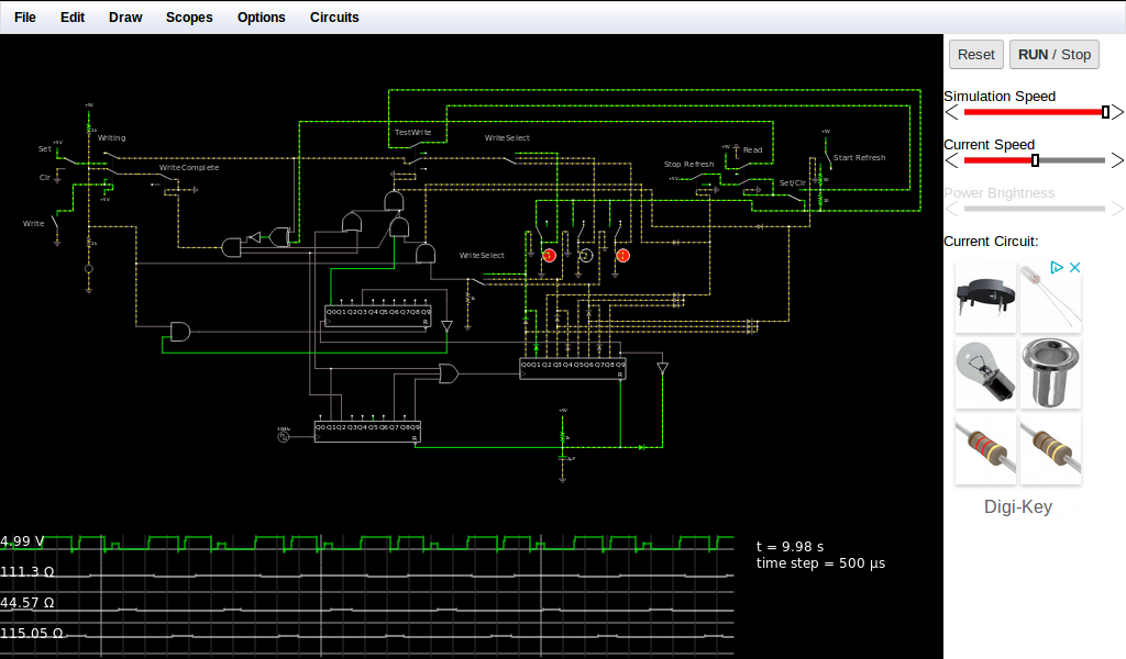
SIMS!
11/26/2018 at 03:19 • 0 comments![]()
(simulation file in this project's files section, or click here and save-as... Then go to the falstad circuit simulator and select File-Open...)
The bottom two decade-counters merely simulate a rotating drum with magnets and reed switches spinning at 10 rotations/sec. Seems realizable. The left one just creates a slight delay between certain states, essentially a larger magnet. Similarly, the relays connecting the bulbs are also part of the drum-simulator.
For each bulb there are three states: Read/refresh-start, refresh, and stop-refreshing.
The third (upper) decade counter is a delay and loop for periodic write-testing. It could be little more than an RC circuit, but here it tests the bit being written periodically until the read-back value matches the value we're writing. This circuit's been optimized for writing that bit as fast as possible, and still allowing refresh of all bulbs as-usual.
I've also added write-hysteresis, by plopping a resistor in series with the bulb or the read-back resistor, depending if writing 0 or 1. Thus the bulb will be written until it's either 10ohms below or above the threshold.
Note that after reaching steady-state Ron is roughly 116ohms, and Roff roughly 44. The readback-threshold seems to be roughly 60ohms. I haven't checked the write-hysteresis thresholds very carefully. That was a late-addition upon finding an unusual case. But, I think it should be quite handy to assure reliability e.g. when the ambient temperature varies dramatically.
It's a lot of circuitry for three bits, but the numbers suggest it could be extended a bit. And... without write-automation the circuit's actually pretty small. Another possibility, maybe, is to use one write-circuit for multiple rows. And, obviously, multiple rows can use the same rotating-drum refresh-sequencer.
Actually, I should clean this up a bit... it looks way more complicated than it is.
-
Multiplexed relay read/write/refresh
11/25/2018 at 01:26 • 0 commentsRan some sims... seems to work.
They're on the computer, kinda too beat to start it up.
Got a bit of feature-creep.
Reading, writing, and refreshing a single bulb requires a single relay, a resistor, pushbuttons, and eyeballs, or hands...
Adding multiplexing for three bulbs adds a rotary-switch for refreshing and another for selecting which to write. This topology allows refreshing in the background without interfering with write... so, throw a motor on the refresh-selector and have at it.
Presently the full refresh-cycle runs at 10Hz. Bulbs rated for Roff=10ohms and Ron=150ohms are asymptoing to around 45ohms off and 116ohms on.
....
Now I get a bit carried away...
wouldn't it be nice to automate the write process? Have it automatically stop writing once the bulb cools/warms enough? Bam: a couple additional relays and some boolean logic (XNOR!).
Ah, let's speed up the process, no need to write a zero when it already is! Sample-first-then-write. Uh-oh, bug. If you start a write of 1 to a 0 at just the right time after its previous 1->0, and at just the right time during refresh, it *just barely* crosses the 0->1 threshold, stops writing, and cools back to 0.
Part of the point of automated-write-testing/completion was to assure such things *wouldn't* happen, e.g. in extremely cold weather. And, ironically, maybe, attempting to avoid that scenario *caused* it.
So, now a further feature-creep... Hysteresis... Let's set a lower threshold for Roff and a higher one for Ron, but only when *writing*. No prob, we already have the relays... two more resistors and add another pole (3PDT, now!)
Or... yahknow, it worked before because it wrote for a while before testing... could just have an arbitrarily-long write-process with a single R/C circuit....
I think I've forgotten some intermediate feature-creeps... But, the point is, it's automated and simulated functional...
A rotary-switch, another on a motor (or a drum with magnets and reed switches), a few relays, and there yah have it, heh!
..
Oh, interesting observation: I used a decade-counter (4017?) to simulate our drum-switch... And using the reset terminal causes the first bulb's refresh-timing to be slightly shortened.
This is actually quite telling, as it reaches asymptotes of something like 10ohms lower than the others... Yet it remains stable and still far from the threshold (currently ~60ohms).
Thus, this seems way more resilliant than I expected, and once that timing glitch is fixed and write hysteresis is functioning (heh!) it should be able to handle at least a few more bulbs. 5x7 may be realistic.
....
Oh, a few feature-creeps actually resulted in a simpler system... That was cool.
I should throw up screenshots and simulation files (TODO).
...
Actually, it seems resiliant-enough that I've pondered multiple values per bulb...
Presently the sims are for a 5V-only system... 5V bulbs (160mW seems reasonable), 5V relays (600ohm coils, similarly reasonable)... But what about going back to an earlier idea...? 120V bulbs, 5V measurement-system... And various DC voltage-sources (rather'n resistors/current sources) for refreshing various values... they can't get nearly as hot at, say, 60V as 120V... Pretty sure bulbs aren't a perfect thermos, and photon-ejection must require some power, otherwise 5V in a 120V bulb would eventually glow white-hot...
Relay-measurement, still? Also, 'spose similar could be done with 5V bulbs and a lot more precision.
-
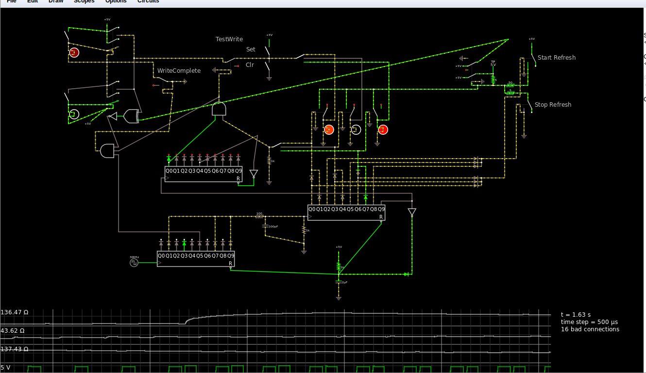
Relay Refresh 2
11/22/2018 at 08:30 • 0 commentsAnother unpublished draft. sheesh!
-----
Got simpler, then went all-out... We're talking multiplexing and Write-Complete testing.
Pardon the Digital logic, Dunno how to make a rotating drum-ROM with magnets and reed-switches in this simulator. And... well... I got lazy with the gates.
![]()
The key, of course, is the refresh/read circuitry, at the upper-right which consist of a single relay and a few resistors.
Herein, I think I've chosen somewhat realistic components, etc... 5V 160mW bulbs, a 5V relay with 600ohm coil, 10Hz refresh.
A few last-minute changes, can't say they've been fully-pondered, but... oh snap... oscillation again? No.
Another key, of course, is finding timings/values that cause the off bulbs' heat/resistance to asymptote, rather'n keep climbing, due to periodic measurement current. I think it's doable with enough slack to not require a lot of precision.
Really, this is a mess, the concept is pretty simple, just need some old cylindrical container, a motor, magnets, and reed-switches for all them counters, diodes, and associated relays.
The write-complete circuitry, though... That's something else. That's a lotta relays and gates. And may be completely unnecessary, depending on the goal. E.G. was thinking of a 5x7 grid where pixels are set by hand. In which case the "set" and "clear" switches could be used manually with a keen eye, and all that testing circuitry removed.
But also have a "big idea" to make my millions from this... so that'd need automation for writing (which, really, could just use a R-C delay circuit...)
-
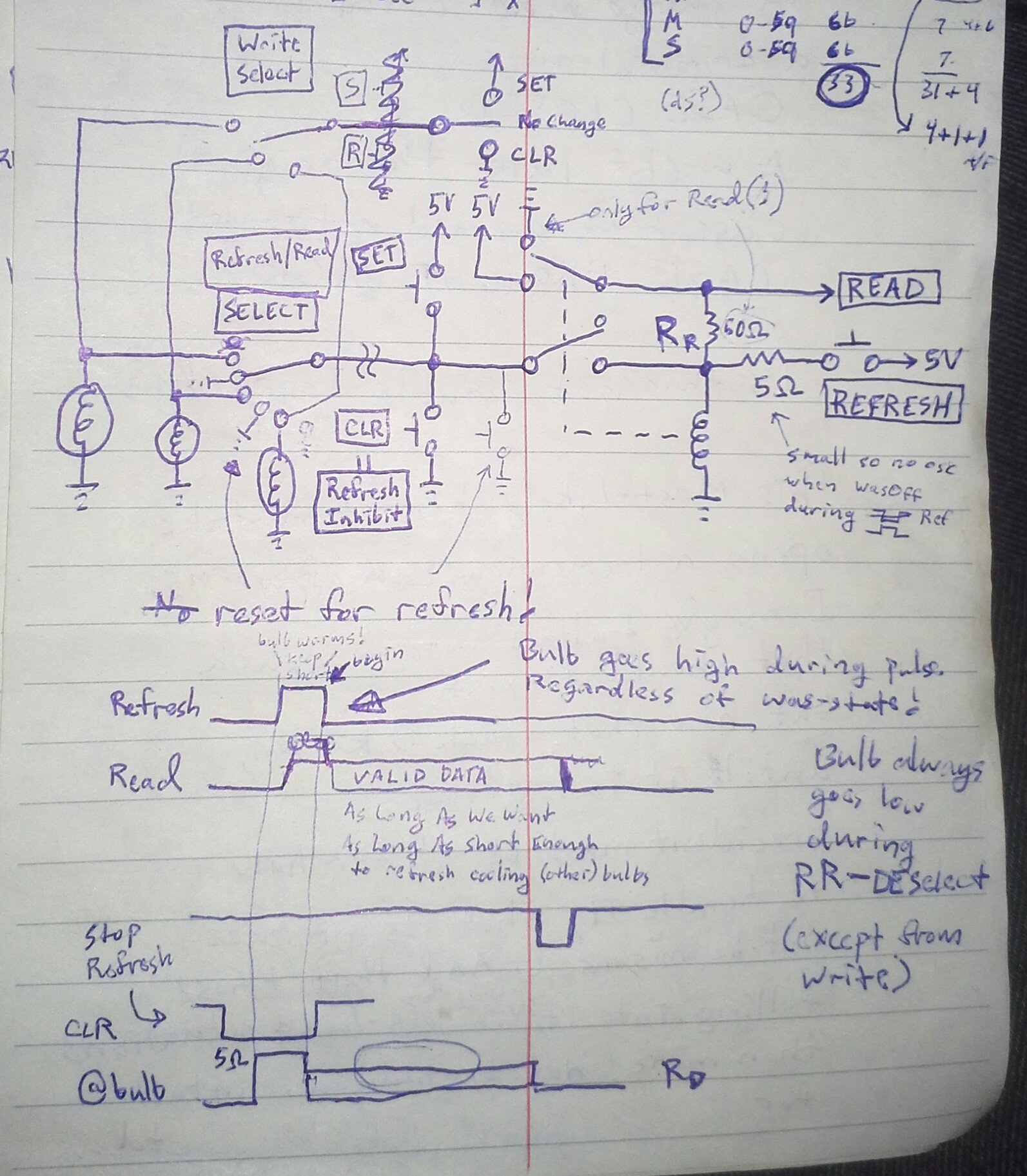
Relay-based Refresh Circuit
11/20/2018 at 05:47 • 4 comments![]()
Heh, thought about drawing it again [again again] cleaner, but there's a lotta info here.
It may be hard to tell, but the idea is to use just one read/write/refresh circuit for numerous bulbs (maybe a row). The Refresh-Select switch is likely to be a motorized-drum with magnets and reed switches. This might also handle timing for the Refresh and Refresh-Inhibit/Stop pulses, as well as another pulse during Data-Valid.Write-select is on a different switch [rotary, likely motorized]. Note that writing safely overrides refresh on the selected bulb, and presently does so as fast as possible... Not requiring the multiplexed refresh circuit to do-so, nor interfering with refresh timing of other bulbs.
(oh snap, 'safely' was before the refresh-reset ... gotta look into that. TODO)
Relays, then, can also be used in the write circuitry, for automation...
Oh, snap... I just came up with another possible change.
Anyhow, was-thinking a 5x7 display might be manageable...
This, of course, all relies on whether bulbs can be found near these specs...
100ohms 5V -> 50mA? Sure... and 1K relay-windings? Seems doable. Induction, heating/cooling-time, thermocouples(?!)... I guess we'll see.
But I've obviously gotten carried-away, already thinking of 5x7, write-complete feedback, counters, and even ISA cards...
How about *one*, hand-controlled light-bit, first.
Might be a while. Might be repurposing a relay or two from under the hood!
Oh, and resistors... these values aren't in my collection, and I'm a ways away from the part-store... I might just scrap some pencils.
(Which, dangit, woulda been *the* solution for the friggin' battery charger!)
Oh yeah, hey... the read-process inherently refreshes and vice-versa... kinda handy.
-
Thermocouple?!
11/19/2018 at 09:14 • 0 commentsInteresting results with a different 12V bulb. These ones seem to measure about 0.1ohms cold, and about 1.5ohms hot. Pretty close to the 1/15 quoted elsewhere.
EXCEPT something weird: The resistance nearly immediately after turning off *climbs* from about 1ohm to about 1.5 after about a second, then falls to about .3ohms after about 3 seconds... and eventually back to 0.1.
What?!
Inductance, maybe?
So, I stopped measuring resistance, and instead measure current... through the bulb, when it's switched Off.
And sure-enough, my meter gives around -1 to -2uA initially, then decays to -0uA in about one second. It takes another 2 seconds for it to read 0uA (without a minus-sign).)
[side-note: interesting plausibly-useful tool for the future: apparently when the meter's display is not precise enough to show a tiny non-zero measurement, it may still have enough measurement precision to at least display the minus-sign... That could be handy!]
So... it would seem a tiny current seems to be interfering with my just-turned-off resistance-measurement.
It could be inductance... Maybe even in my meter-leads and-or the wiring to the bulb... Though, If I understand correctly, the fact it's negative suggests it's coming from the bulb's filament.
But... something even weirder: When I allowed the bulb to cool, then turned it on only briefly, then ran the measurement, I got -4uA!
This, I first figured was due to my *really wonky* Turn-off-then-touch-probe test-setup... Maybe it was initially -4uA each time, but I wasn't touching the probe fast enough to see...
But those larger currents didn't seem to take any longer to drop to -0. Infact, the display-update rate had it drop straight from -4uA to -1uA in what seemed one measurement time, just as it did in dropping from -2uA to -1uA, before.
Also... I tried being quicker with the turn-off-then-touch procedure, while having a longer on time... and did not see -3 or -4uA.
Repeat: for longer "on" times, I was getting up to -2uA. For shorter on-times I saw -3 and -4uA.
This ain't inductance...
Then I remembered @Starhawk made mention of thermocouples... And, well, there are different metals involved. The difference between the filament and support-metal inside the bulb can't be responsible since it's symmetrical. But, the base is brass, and the nub isn't.
And That might just explain it... A short on time would result in a greater temperature *difference* between the inner-bulb-metals and the base. A longer on time would allow the base to heat up with the inner metals... the temperature-difference would be smaller, and thus so would the voltage of the thermocouple (right?).
There probably are inductive effects, as well, maybe even accounting for some large percentage of the 2uA... but I'm pretty sure we're seeing something else, here, Thermocouples makes sense.
.
I still have ziltch clue as to the other bulb, of the last log. That was weird.
.
This bulb is big, slow, and power-hungry... I guess I was pretty lucky all these factors were measurable with a wonky setup and a multimeter.
So, one should now, at least, have a better idea of things to look for when experimenting with new bulbs: 1/15 *resistance* may not be the biggest factor to consider if using milliseconds to read/refresh!
-
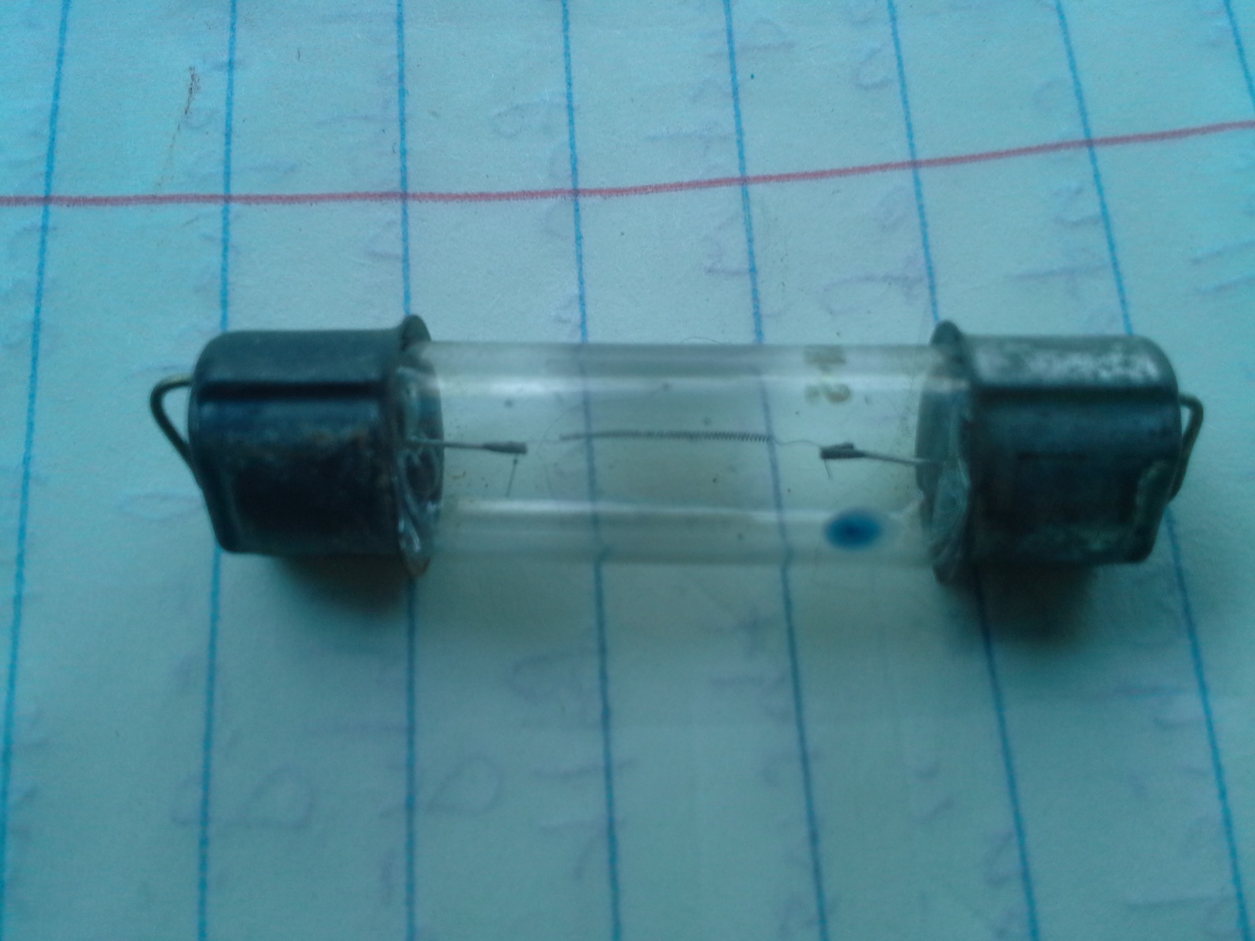
Reality-inversion?
11/18/2018 at 22:10 • 0 commentsAlright! First experiments run...
Used the dome-light in my van... 12V, DC, unknown watts/amps.
Summary: Resistance DEcreases with heat, INcreases as it cools.
Reality inverted, or something.
![]()
It takes a couple seconds to return to normal (cold) resistance of around 1ohm... So, there's "memory" there, just not as-expected.
I guess we also have an inductor... But, really?
And... say they did use a different material where resistance decreases with heat... wouldn't it just burn out? Hmmm.
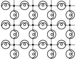
This inverted-case could, however, be beneficial... Say one wishes to refresh a bulb in a grid (ala @roelh 's "challenge" and image on this project's front-page), surrounding that bulb are three others, roughly in-series, to the left, and three others again in series to the right.
![]()
In the *expected* case, where resistance increases with heat, we might, say, have 100ohms on our recently-lit (binary 1) bulb, and 10ohms on all the others (they were off, binary 0). That'd (roughly) give 3 parallel resistive paths of 30ohms, 100ohms, and 30ohms. Powering our bulb to refresh/reheat it, then, would send more current through our off bulbs than through our on bulb, possibly heating them enough to toggle their value (as measured/thresholded).
OTOH, in this case, where resistance appears to DEcrease with heat, the surrounding 'off' bulbs will get *less* current than the bulb we intend to refresh/reheat.
That's ideal. But definitely not what was expected... So, it may be that, really, we're not messing with heat-memory but magnetic-memory (inductance), or some combination(?).
Does it matter?
Well, for one thing, it suggests that the bulbs' characteristics may play a major role in the circuitry. So, buy and experiment with ones you can easily get in bulk!
-
Some Resources
11/17/2018 at 22:41 • 0 commentsSearch-fu was *awful* a few days ago. But eventually it came full-circle, so here are some great resources:
https://forum.allaboutcircuits.com/threads/incandescent-light-bulb-inductance.117357/
http://it.stlawu.edu/~koon/classes/221.222/222L/Stefan.html
https://www.physicsforums.com/threads/inrush-current-filament-electrical.266664/
http://physlab.org/wp-content/uploads/2016/03/Planck_ref8.pdf
https://www.physics.utoronto.ca/~phy224_324/exercises/NonLinearElements/Nolin_elements.pdf
-
Stable States
11/17/2018 at 20:11 • 8 commentsCarrying on discussion from this project's front page from @DeepSOIC
![]()
DeepSOIC wrote 20 hours ago
Once upon a time, I thought, that there can be a lightbulb, that, if powered with a constant current source, will have two stable states. In one, resistance is low, and I^2*R is not enough to heat it up. And if it's hot, R is high, it dissipates more power, and sustains hotness.
I have never found a bulb that would do it though. I'm pretty sure, a thing somewhat like that can be achieved with paralleled leds, provided enough heat isolation of each led.
@roelh wrote an hour ago
I tried this once (with series resistor instead of current source). Once connected, the brightness of the lamp came up very slowly. It might be used for a time delay ! But indeed, no two stable states.
A lamp has a positive temperature coefficient. But would the two-state effect be possible with an NTC resistor ?