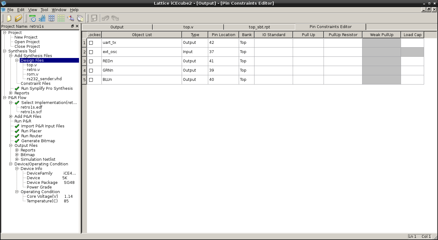
Full project for iCEcube2 software for iCE40UP5K-SG48 FPGA on UPDuino v2.0 board:
https://cdn.hackaday.io/files/1623976947993248/iCEcube2-retro1s.tar.xz
It's Retro-V v1.0.0 soft core with the same "Hello RISC-V!" test program, but running on external 12 MHz (taken from 2nd pin from the right bottom) and with RS232 sender ( also provided by @Frank Buss ):
https://github.com/FrankBuss/adc4/blob/master/DDR3_RTL/rs232_sender.vhd
12 MHz should be connected to pin 37 (7th pin from the left top) and pin 42 is TX:

This is top.v that connects everything together (RS232 sender puts CPU on hold every character while busy):
module top(ext_osc,uart_tx,REDn,BLUn,GRNn);
input wire ext_osc; // 12 MHz
output wire uart_tx;

output  wire        REDn;       // Red
output  wire        BLUn;       // Blue
output  wire        GRNn;       // Green

reg [27:0]  frequency_counter_i;

wire [15:0] address;
wire [7:0] data,dataout;
wire clk,wren,hold,res;

always @(posedge ext_osc) begin
    frequency_counter_i <= frequency_counter_i + 1'b1;
end

assign clk = ext_osc;//frequency_counter_i[22];

retro cpu (
.nres(1'b1),
.clk(clk),
.hold(hold),
.address(address),
.data_in(data),
.data_out(dataout),
.wren(wren)
);

//assign addrout = address;

assign res = (address==16'h0)?1'b1:1'b0;

// RS232 sender by Frank Buss:
// entity rs232_sender is
//    generic (
//    system_speed, -- clk_i speed, in hz
//    baudrate : integer); -- baudrate, in bps
//    port (
//    clk_i : in std_logic;
//    dat_i : in unsigned(7 downto 0);
//    rst_i : in std_logic;
//    stb_i : in std_logic;
//    tx    : out std_logic;
//    busy  : out std_logic);
//end entity rs232_sender;

rs232_sender #(12000000,115200) TX (
.clk_i (ext_osc),
.dat_i (dataout),
.rst_i (res),
.stb_i (wren),
.tx (uart_tx),
.busy (hold)
);

//rom #(10) prog (clk,address[9:0],data);

rom prog (address[7:0],data);

SB_RGBA_DRV RGB_DRIVER (
      .RGBLEDEN (1'b1),
      .RGB0PWM  (hold),//GREEN
      .RGB1PWM  (clk),//BLUE
      .RGB2PWM  (wren),//RED
      .CURREN   (1'b1),
      .RGB0     (GRNn),
      .RGB1     (BLUn),
      .RGB2     (REDn)
);
defparam RGB_DRIVER.RGB0_CURRENT = "0b000001";
defparam RGB_DRIVER.RGB1_CURRENT = "0b000001";
defparam RGB_DRIVER.RGB2_CURRENT = "0b000001";

endmodule
Serial output configured as 115,200 8N1 and it's printing this in terminal:
Hello RISC-V!
Hello RISC-V!
Hello RISC-V!
Hello RISC-V!
Hello RISC-V!
Hello RISC-V!
Hello RISC-V!
Hello RISC-V!
Hello RISC-V!
According to iCEcube2 output, soft CPU here can run on up to almost 20 MHz:
#####################################################################
                     Clock Summary
=====================================================================
Number of clocks: 1
Clock: top|ext_osc | Frequency: 19.98 MHz | Target: 36.62 MHz
=====================================================================
                     End of Clock Summary
#####################################################################
But RISC-V program is still running from combinational ROM, so it is not yet a REAL thing with variables (other than registers), stack etc...
 SHAOS
SHAOS
Discussions
Become a Hackaday.io Member
Create an account to leave a comment. Already have an account? Log In.
BTW, I would make the busy bit available as a memory mapped value, so that you can check it with RISC-V assembly code, or even generate an interrupt when it changes. Then you wouldn't need to block the core. And you could even add a hardware FIFO.
Are you sure? yes | no
Probably yes, I can do something like that, but for now I simply needed existing sample code to work :)
Are you sure? yes | no
Looks good. But Hackaday should really add syntax highlighting for Verilog and VHDL.
Are you sure? yes | no
yes, they should :)
Are you sure? yes | no