SimpleTronic
Watch the Video:
Schematic:
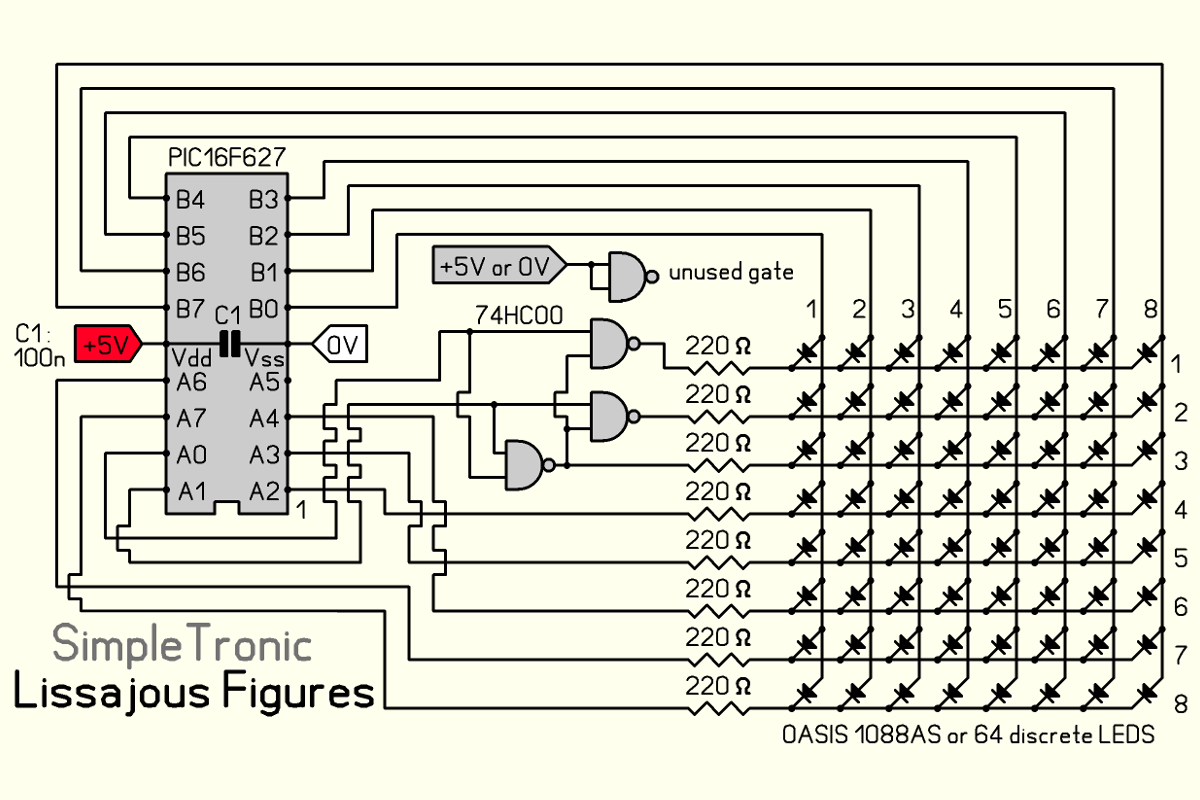
Leds are driven by PIC16F627 ports and 74HC00 nand gates.
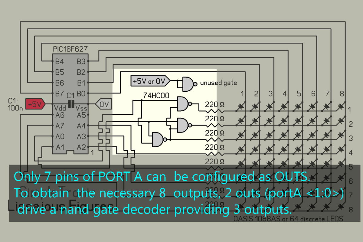
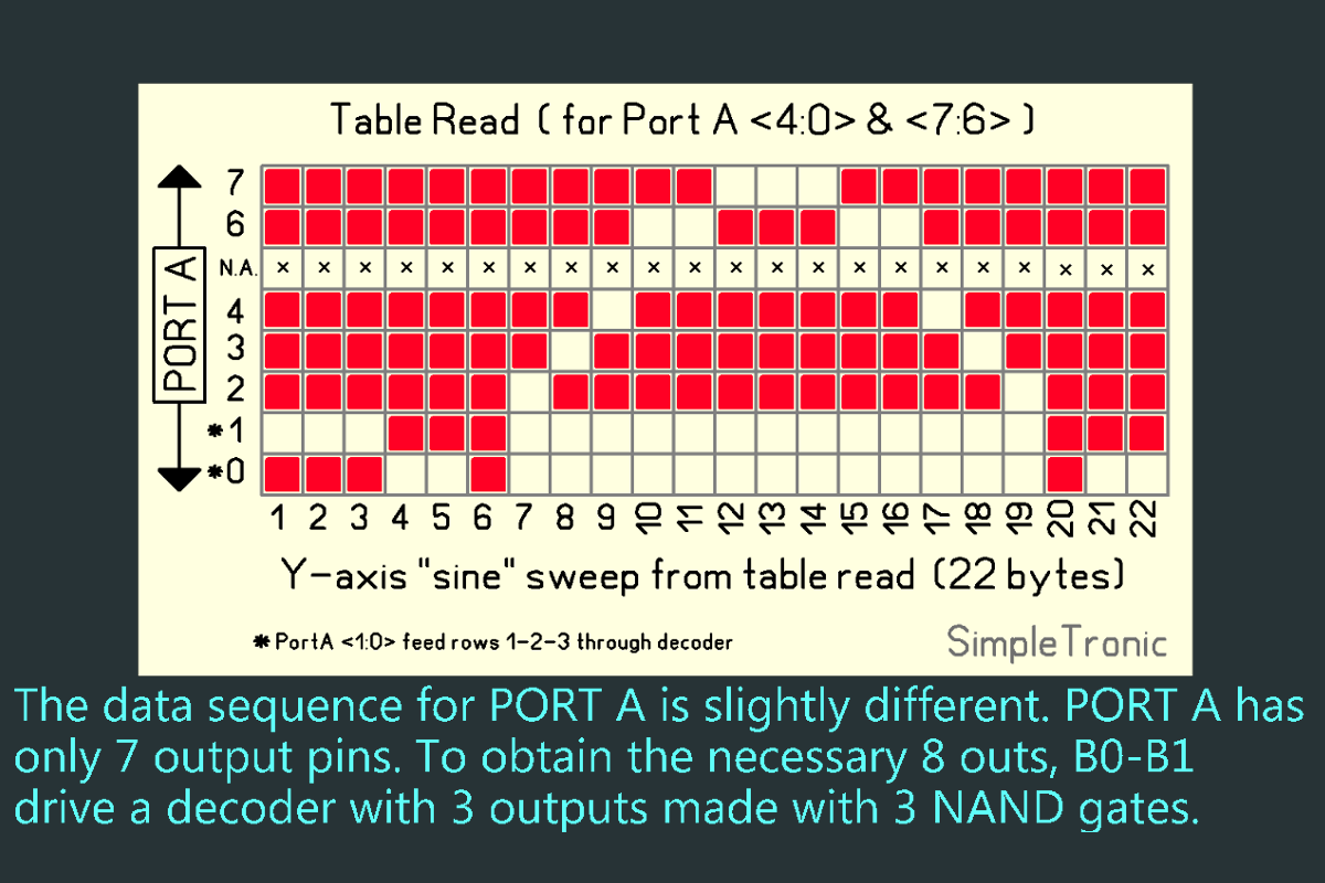
PORTB pins of the mcu drive the 8 common anodes (X-axis). PORTA (Y-axis / LED cathodes) has a maximum of 7 pins configurable as outs. To obtain the necessary 8 outs, 2 pins PORTA <1:0> drive a decoder made with 3 nand gates (74HC00) which provides 3 outs from 2 pins of the mcu.
Decoder:
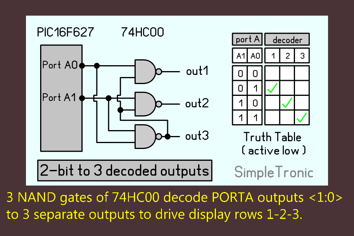
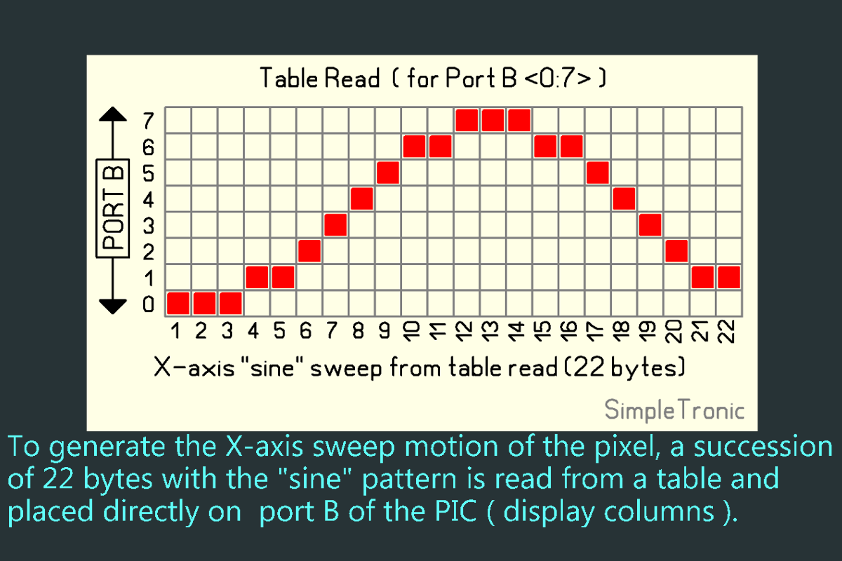
Wave generation (X / Y axes) :
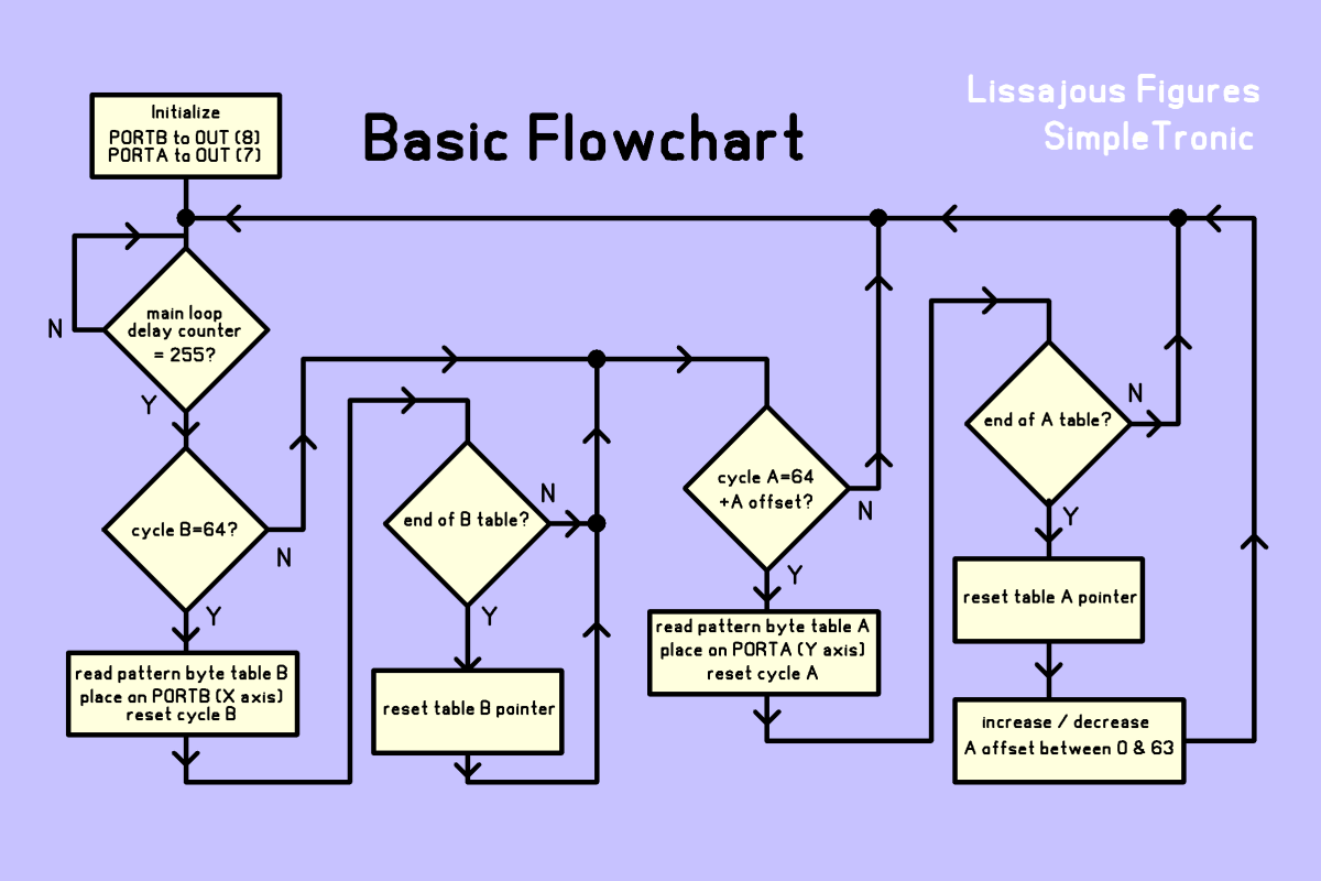
The "sine" motion of the pixel is obtained by reading a succession of 22 byte patterns from a table in memory for the X-axis and the Y-axis respectively. The rate at which these patterns are read determine the period of the sweep.
Basic Flowchart: