I just started my 11 day holiday vacation, allowing me to spend more time on this project. First step is manufacturing of the actual board. I noticed on the stencil that the solder pads for the USB connectors are part of the stencil as well, something I did not do on my other projects. It actually worked out great, because the solder paste that is pushed into these through holes are holding the USB connector very well, and no second operation is necessary.
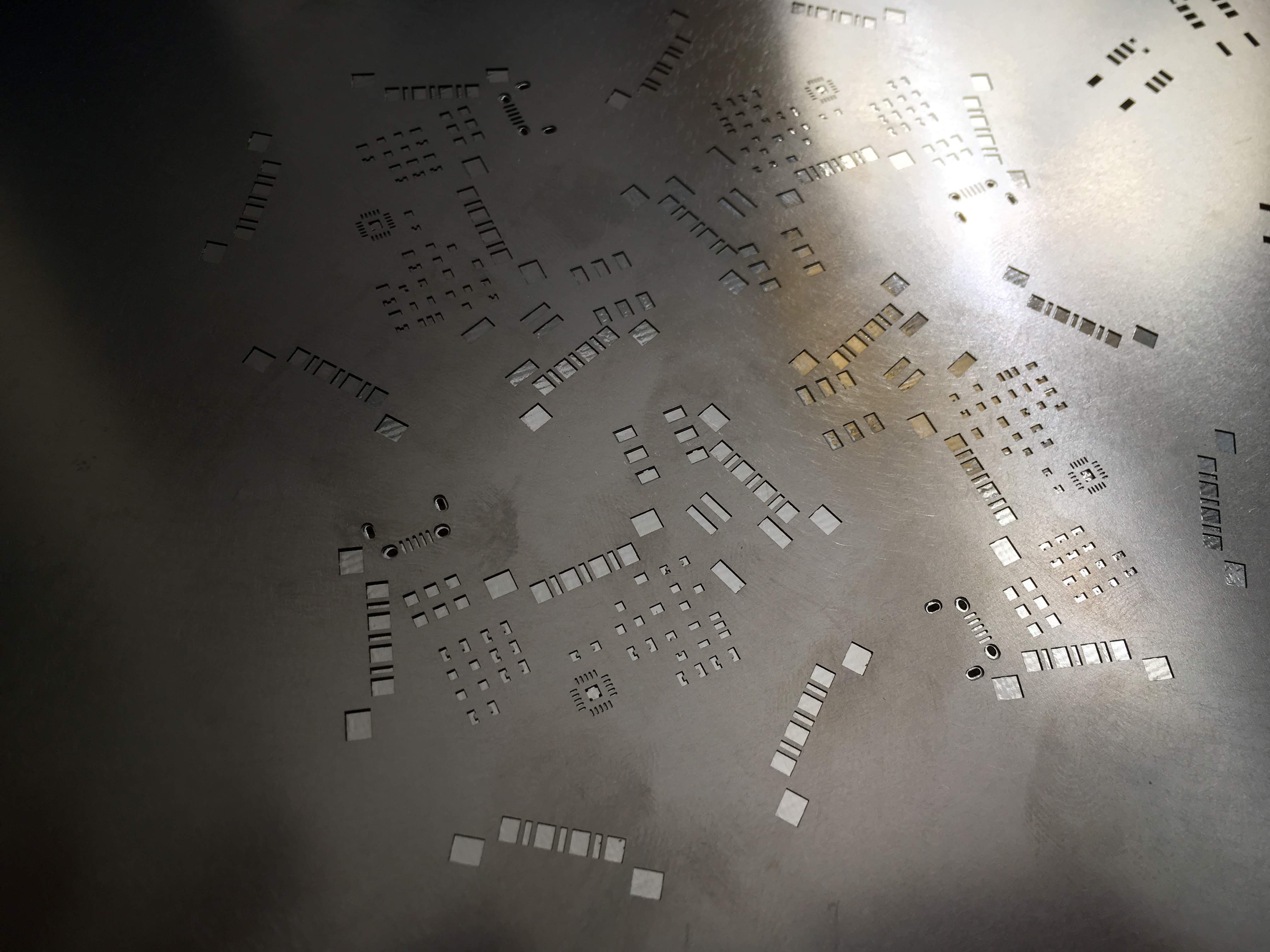
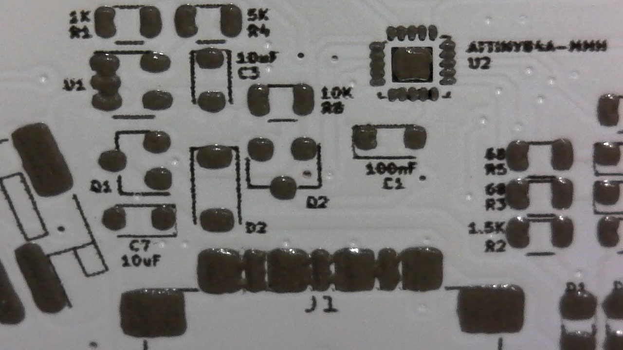
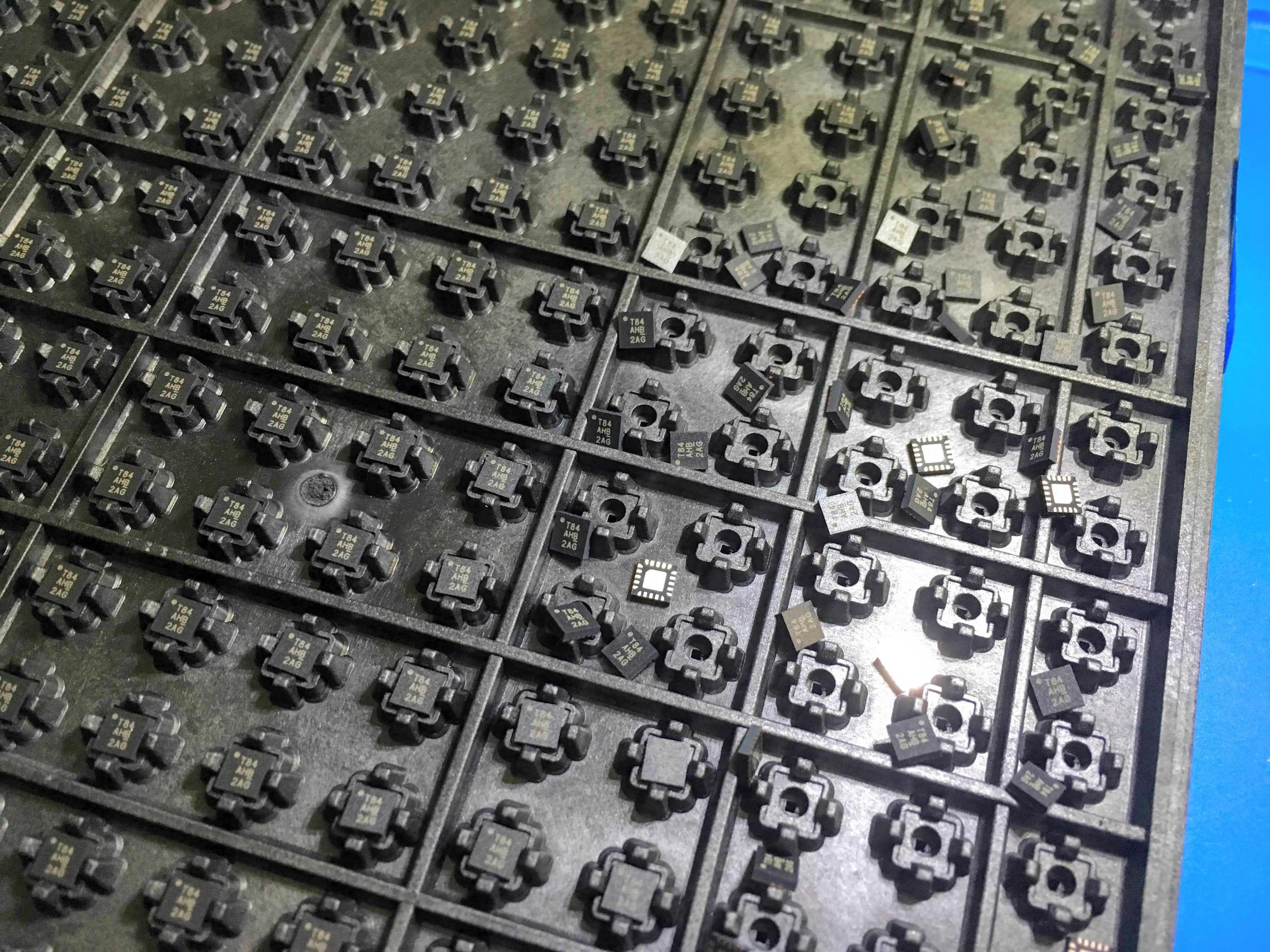
Just before I got ready to place the components I bumped into the tray of the ATtiny84a micro-chips. See here the results of bumping into the tray:
And here are some pictures of the board after placing most of the components. The battery connector and switch are still missing, but those are easy to place after they get in.
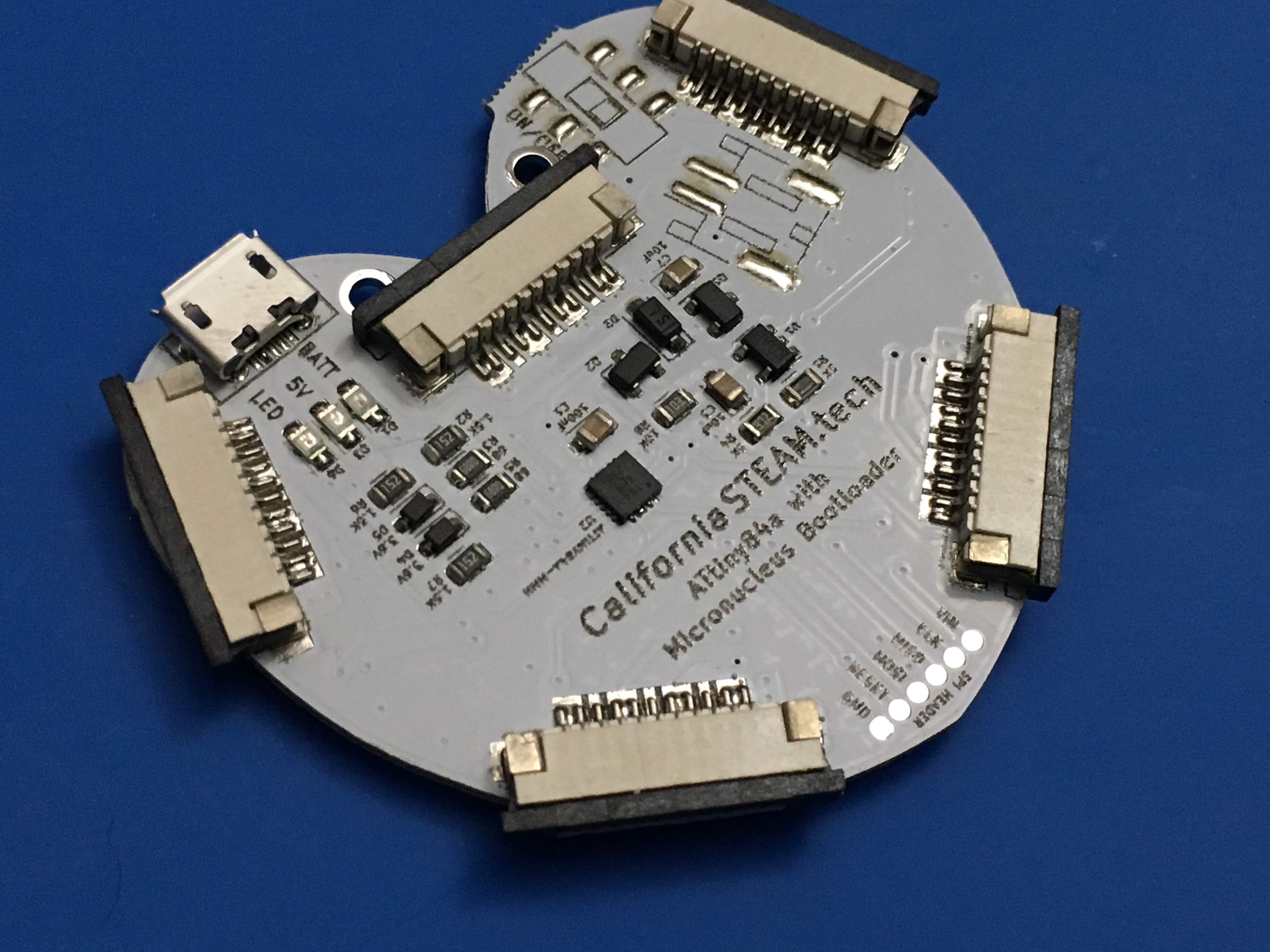
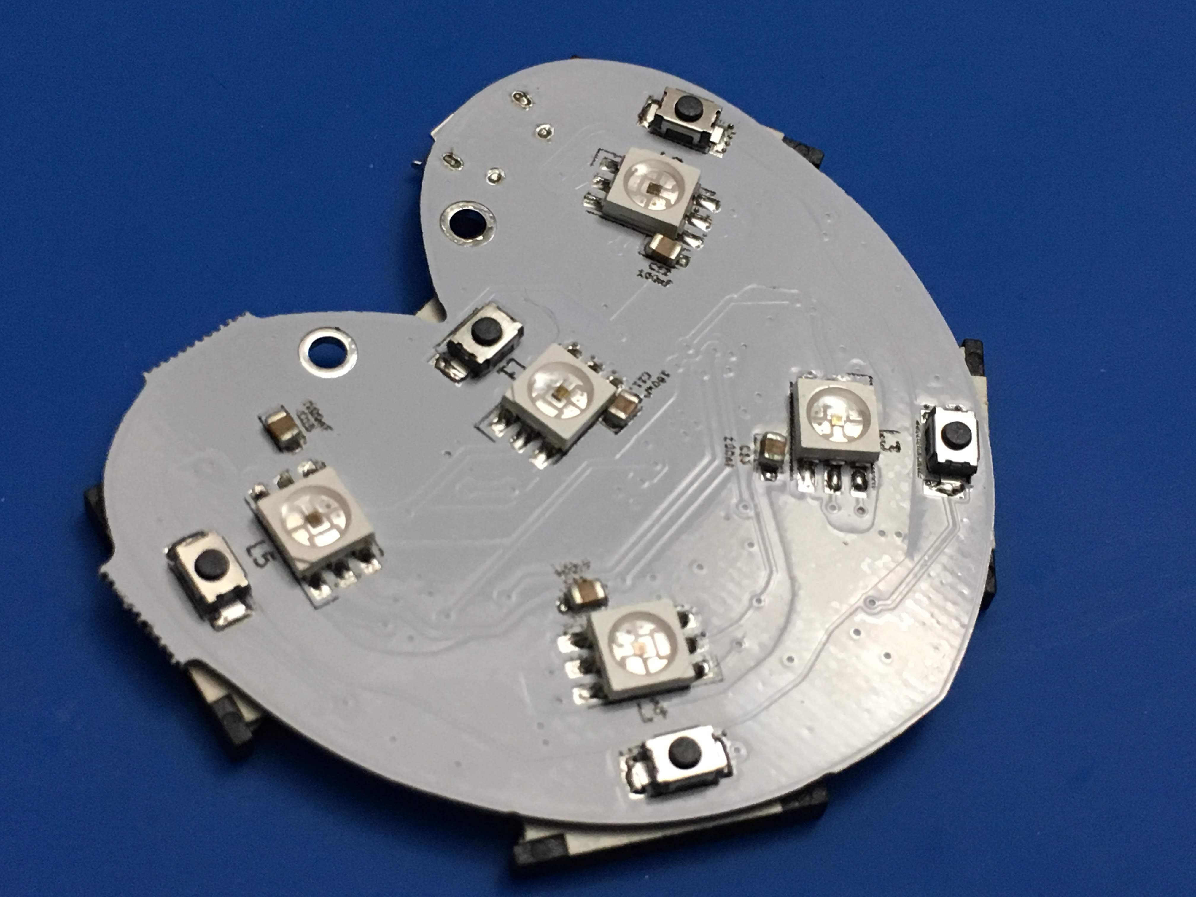
I still needs some manual touch-up since not all the LED's are connected correctly as you can see in the picture above.
Next step is uploading the firmware and check the hardware.
 Sander van de Bor
Discussions
Become a Hackaday.io Member
Create an account to leave a comment. Already have an account? Log In.