Suppose, for the sake of argument, that you want to create a digital silicon chip, for example. The exciting ASIC world is calling your name so your RTL code is tested, formally verified, simulated, cosimulated, and finally synthesised.
At that point, you would want to ensure the synthesiser did not poo-poo your neat system so you can re-simulate the mapped netlist, using the fast mode of this library. Or you can simply write and pre-map some modules in this low-level dialect, as I do.
Fast mode
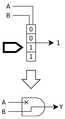
In this mode, each logic gate is replaced by a lookup table of the appropriate size.

Fast mode doesn't care much about meta-values, "if it's not 1, it's 0" to speed things up. Be ready to break your code, and in the process, uncover potential troubles with badly initialised registers (for example, and if your synthesiser didn't warn you enough before).
Now your code works in after-synthesis. But it's only the beginning of the end of the road because going from the virtual world to the real world implies a crazy shift in methods and focus, and I'm not even talking about place/route/retiming and other niceties... Because here, we're out of the comfortable walled garden of FPGAworld, where they sell you "Known Good Dice" that will behave exactly according to the specifications of the datasheet. No, the factory will deliver dice, some of them might even work !
How would you know which are good ? Run a program, for example, and see if it returns the expected good value : that's a valid idea but it can work only if the die is totally connected to the outside world... and this is costly, particularly if the die is DOA ! The usual solution is to connect only a few pins to a test rig, power up, inject signals and check the results. If the circuit looks like it's not dead and passes enough tests, it can then be packaged for further thorough tests.
Trace mode
One of the approaches for testing the chip with only a few pins is to make it run some sort of internally-generated sequence or even program that will exercise all (or most) units in the chip. It's called "BIST" for Built-In Self-Test and it must be designed along with the chip itself (remember the "Design For Test" DFT methodology they bore you with ?) so you're not caught with untestable units at the last moment.
So the chip must be designed in advance to allow self-testing, which means you must synthesise often and run/simulate the BIST to ensure that ALL the gates are covered. This scenario is covered by the second mode of the library: trace mode that works with both normal and meta values. When one meta-value 'L' or 'H' is found at the input, the output will be a valid meta-value, so it propagates a meta-state in the logic cone. You can either set an input pin to meta, or select one input combination to output the corresponding metavalue. All the computations should be performed correctly, right ? At least you should observe a number of meta-values at the output to see which input or gate affects which output bit.
Hopefully, this should help you design, adapt, refine and select your BIST methodology.

For now you can only select one bit to "meta-ise" but it shouldn't be too hard to brute-force a small design, you can even run multiple GHDL instances in parallel, though that's only the beginning.
Flip/Alteration mode
Once you have selected your BIST method and built your test vectors, you need to test them exhaustively. You synthesise again and now you simulate over and over, with each iteration altering a different bit in the LUT of all the gates. Each time, one bit is flipped, which might subtly change the function of the gate and the whole circuit... Meta-informations are propagated like with the trace mode but no new meta-value is injected. However the change of any gate should result in at least one invalid result at the output.

This is the most useful mode so far because it simulates the imperfect world. Furthermore, an exhaustive test might not be really expensive because the test time grows with the number of gates (times inputs per gate), not the number of available states. And as stated before, you can run as many parallel instances of GHDL as you like !
Probe mode
BIST is great but there might not be the required size or time or even possibility to let the chip test itself. In this case, you'll have to inject the test vectors all by yourself. And this time, time is even more critical because 1) testing time is expensive (you don't want to spend more than a second testing each chip, on a machine you pay by the hour 2) bandwidth is limited by the few pins and you can't observe the circuit running at full speed. So you have to select the fewest test vectors possible that still ensure the circuit is (sufficiently) functional. You can't let the circuit itself generate hundreds of millions of vectors with 1% chance of hitting any possible new fault : each additional vector must hit at least one fault that was not covered by the last vectors.
As stated before, the maximum theoretical number of test vectors is the total number of gate input states. If you have 1K gates with 3 inputs each, that's 8K vectors, however many can be fused because they are either redundant or also test neighbour gates. OTOH it's not easy to get the optimal set of test vectors but there are many heuristics that help reduce the number anyway.

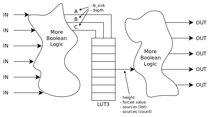
But before we can build or design the test vectors, whatever the strategy, we need to have the full netlist of the design. We already have a gatelist from the previous modes and they control the outputs at will, though yet under the control of the LUT. It takes little effort to decouple the input from the output and selectively control the output value while also logging and processing the activity on the inputs. That's the probe mode which requires a different running environment : instead of simulating the design with actual test vectors, the netlist extractor processes the gates individually. It's a conscious choice to not examine the RTL source file itself, but run it because you never know, there would be sub-units and all kinds of non-obvious things, in case we don't get a flat netlist. We can access each gate individually and that's all we need yet.

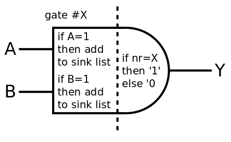
Each time an input changes on each gate, the output value is evaluated by a function whose behaviour changes according to the mode. In the probe mode, the value is checked and added to a log, while the output changes to signal itself to the other gates. In the above diagram:
- The output is set only if the gate is selected (its number matches the selected gate number), otherwise it's reset to 0. Thus all the sinks to this gate will receive '1' only from this gate and they know they are connected to it.
- Each input is read and if the value '1' is found, then the number of the current gate is added to the list of sinks of the emitting gate.
Given the list of all the gates, it's easy to scan it and run a test for each of the gates.
Now, it's not as easy in practice and the implementation has some tweaks and tricks.
- You can't change the gate's output at will. There is no way to explicitly send/trigger an event to refresh the gates. You have to do it implicitly by changing the value of the inputs. I have allocated 2 values of the type std_logic_value for this purpose (for the output to change and force the refresh of the output) : 'U' and 'X'. This also means that the output will be either 'X' or 'U' (following the current cycle) and not '0' as in the example.
- 'U' and 'X' are used but we can still use 7 other values from std_logic_vector ! So we can test simultaneously 7 gates with the values '1', '0', 'L', 'H', 'W', 'Z' and '-'. This speeds up things a bit. Unfortunately, the netlist can't be extracted all at once because std_logic has only 9 values and we can't re-cast the DUT (that would have been too easy, right ?)
- The DUT must be inside a sort of wrapper, which I can't yet automatically design but Tristan Gingold told me there is a way, using methods that are not (yet) familiar to me. Time will tell but for now, I'm doing it by hand.
The probe mode is used to extract the netlist, which is then used to generate test vectors. The DUT is then run again in Flip or Trace mode to verify the coverage of each vector : each vector tests at least one gate in a given configuration throughout the whole logic depth for the input to give an observable output and these gates can be crossed out of the list of configurations to check/test with the following vectors.
TODO
Now that we can peek into every net and gate, it is possible to count how many times or often the states changes. This is useful to evaluate the power savings of a given architecture or estimate how much the circuit will draw from dynamic vs static current.
The "toggle" mode should be implemented someday...
 Yann Guidon / YGDES
Discussions
Become a Hackaday.io Member
Create an account to leave a comment. Already have an account? Log In.