 gertux
If you need more than the standard broken out pins and are not afraid to solder, small changes can bring some nice extras.
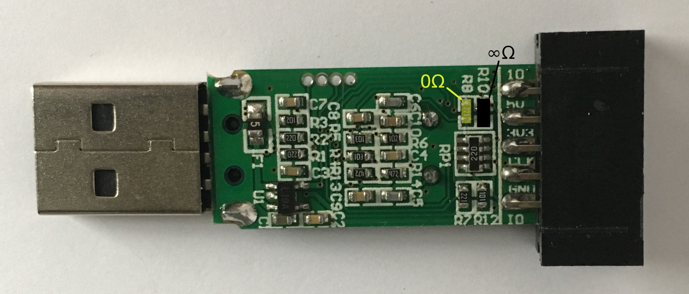
If you replace resistor R8 with a 0Ω one or a solder bridge, you connect both MCU pin 43 (PB7) and MCU pin 46 (PB9) with connector pin 5 (SWIM). It's probably also a good idea to remove the 680Ω pull up resistor R10 just next to R8 if you don't need it for you application.
With this simple soldering action you can now use USART1 on pins 42 (TX) and 43 (RX) or even I2C1 on the same pins 42 (SCL) and 43 (SCA) if you manage to sort out the I²C bus pull ups externally.
Discussions
Become a Hackaday.io Member
Create an account to leave a comment. Already have an account? Log In.