The main 'scene' that I play in is at church where we will almost always use IEMs for monitoring. In order to be able to communicate with the band I need a talkback microphone - a mic that is routed to all the musicians IEMs but not Front of House so that I can talk to them without the congregation hearing.
We have been making great use over the last few years of a Radial Hotshot mic switcher - this allows a single microphone to be used for both vocals and talkback.

The output of the mic goes in to the hotshot which then has two outputs - one to the vocal channel of the mixing desk, the other to the talkback channel. When the button is not pressed the Hotshot routes the microphone to the vocal channel and when it is pressed it goes to the talkback channel. Simple and really useful.
Part of creating the STJORN controller (and system around it) is to try and remove as many complications when actually playing as possible. One way is to cut down on the number of different footswitch devices at my feet - currently three; a controller for my guitar rig, one for tracks, and the hotshot.
As such, the idea came to include a mic switcher within the STJORN footcontroller - that way I would have all three pedals in a single unit.
It took a little bit of searching, but I eventually found a circuit diagram for a mic switcher that had some good comments that it worked well. That circuit is thusly:
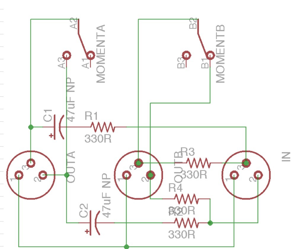
It's a pretty simple circuit. A DPDT switch is used for the switching and the circuit works by shorting out the two hot signals of the 'unused' mic channel. NOTE: The capacitors are NOT polarised as is shown - I can't find where I got the diagram from, but the comment was that when the creator made the diagram he couldn't get it to add non-polarised symbol. I've made this with non-polarised caps and it works!
In the hotshot the switch is a mechanical footswitch and initially this is what I was going to use. But then the thought came that I could use a footswitch through the Teensy to control the mic switcher via a relay. This then opens up some interesting control possibilities such as using a double tap to latch the relay if I need to talk for extended periods, indicating the status of the switch using one of the NeoPixels, controlling the switch via MIDI, etc.
A bit of reading up on the design of relay circuits and the following was designed:
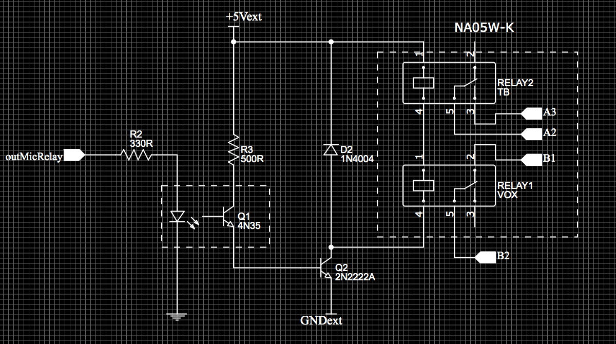
To start with, I wanted to ensure that the audio was kept as noise-free as possible. As such, the circuit design is fully isolated from the rest of the electronics within the STJORN controller. The first part of the isolation is that the signal from the Teensy to control the circuit goes through an opto-isolator. The second is that the +5Vext and GNDext which power the relay are from a 5V-5V DC-DC converter. This provides an isolated 5V and GND just for the relay circuit. Thirdly is, of course, the relay itself which separates the audio circuit from the others. This is most likely overkill but for the sake of a few extra components it was easy to design in and should help keep the signal nice and clean.
The circuit itself is pretty simple:
- The signal from the Teensy comes in to the 4N35 opto-isolator via a resistor - the resistor is required as the opto-isolator has an LED inside so, as always, a resistor is required to limit the current
- Note: the schematic shows a 330R on the input to the 4N35, I actually used a 470R in the end; either is fine; just run the calcs using V=IR
- An opto-isolator works by using the input signal to light an LED within the opto-isolator IC
- On the 'other side' of the IC is a photo-transistor which reacts to the light from the LED.
- When light is present, the photo-transistor base allows current to flow from the collector to the emitter and current flows around the circuit.
- When the light turns off no current is allowed to flow and the circuit is turned off.
- As there is a literal air-gap between the LED and the photo-transistor, this component allows complete physical isolation between circuits.
- The 500R resistor on the input to the photo-transistor is there to limit current; again, I actually used a 470R here
- For the relay circuit itself, the emitter of the opto-isolator is connected to the base of an NPN transistor
- When the opto-isolator is active, the current in the circuit opens the base of the NPN transistor and allows current to flow from +5Vext to GNDext
- The presence of the 1N4004 diode means that the current from +5Vext to GNDext flows through the relay
- Thus, when the opto-isolator is active, current flows through the relay and energises the coil - when the opto-isolator is off the relay opens
- The 1N4004 diode is there to protect the circuit against 'flyback' voltage when the relay opens
- This can cause very high voltages in the circuit and the diode creates a loop circuit to protect against this
With the two circuits designed, it was time to put them together in a stripboard layout. I used the excellent DIY Layout Creator to do this :
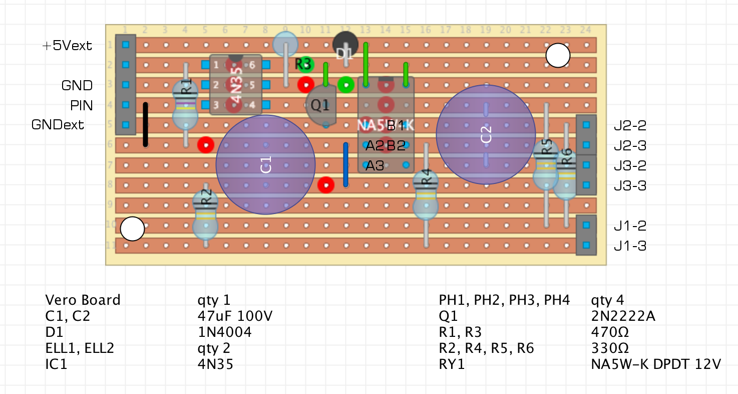
A note on the design - it all was nice and clean until I soldered it up and realised I had the +ve and -ve of the relay the wrong way round.... This lead to the modifications shown in green at the top of the board to reverse this; fortunately a relatively straight-forward task. The takeaway from this is ALWAYS READ THE SPEC SHEET PROPERLY!
The 4N35, 2N222, and relay are all socketed so that I didn't damage them when soldering. The rest is hard-soldered to the board.
As part of trying to work out why it wasn't initally working (due to the relay being inverted...) I also added an LED to the relay circuit. This is driven by the transistor in the same way the relay is so gives good indication if the circuit is working. The LED is socketed as I didn't need it in the circuit all the time but is useful for debugging. It fitted nicely in the space at the top left - I shall leave you to work out the mods needed to fit it in if you want to do the same :)
And here is the circuit all wired up to be tested:
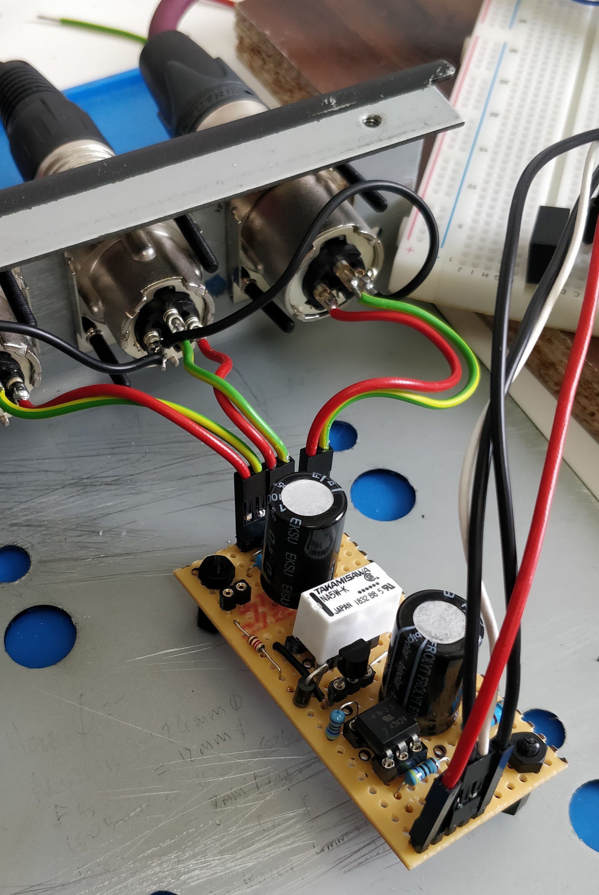
Once the initial kerfuffle with the relay was sorted it worked brilliantly. I tested it by hooking it up to my interface and using a modification of the simple Arduino 'blink' code to turn the relay on and off every few seconds and it works really well. Nice and clean and quiet.
This should be a really useful addition to the controller once it is fully plumbed in and coded up and I am glad I decided to add it in.
Splendid.
Discussions
Become a Hackaday.io Member
Create an account to leave a comment. Already have an account? Log In.
Hey bro, can you help me? I need to do 2 of these for my worship ministry, and sorry about my English, I'm Brazilian and I don't speak it well Can you contact me on discord?
My dc: luciano_bellaver
Are you sure? yes | no