 Bud Bennett
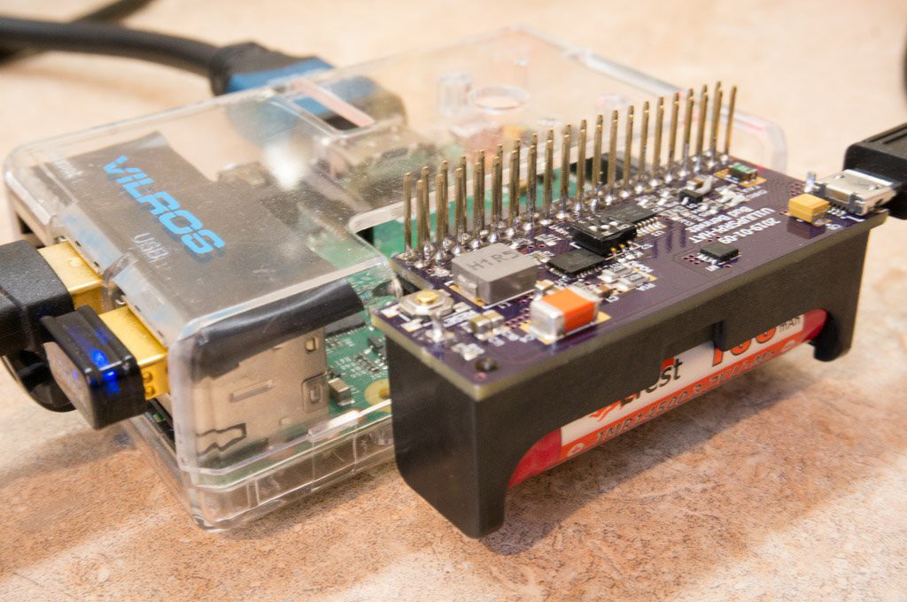
These PCBs are technically the second pass, but I never assembled the first pass PCBs because they did not have the proper cutout to fit the case for the Raspberry Pi.
Executive Summary:
The performance, as far as tested, meets the design objectives. There is one functional failure -- the RESET function doesn't put the part to sleep when power is not applied -- the fix is easy but will require another PCB turn.
Functional Testing:
- When the battery was inserted, or the RESET button was pressed, the circuit immediately went into backup mode by providing output power via the battery. I was expecting the part to enter sleep mode waiting for power to be applied. Pressing the RESET button caused the circuit the enter backup mode until it was released, then the output voltage would fall for a second but then recover back to backup mode. The cause of this phenomenon was that R15 was connected to GND, so when RESET was pressed and the PIC outputs all went to high impedance the LTC4040 was enabled instead of disabled. The fix is to connect R15 to either BAT or the PIC's VDD supply. I cut R15's trace to GND and rewired it to BAT and this problem went away. This fix will require another PCB pass.
- The primary ability of automatic switchover to battery power appears to work well. I've been testing this function on a Raspberry Pi Zero W for a couple of days without a glitch.
- All of the PIC code appears to work well. The I2C interface is transmitting all of the new status bits and the Raspberry Pi can easily decode them without error. The PIC properly controls the on/off state of the LTC4040 and responds when the ACPR line is pulled low by the LTC4040. It also properly detects ACPR when in sleep mode. The PIC code doesn't appear to require any changes for functionality.
- The battery charger is functioning properly. At first the charger current was very low because the PROG pin was not connected. A bit of re-soldering fixed it. The DIP switches alter the charge termination voltage to correct levels. The Charge LED and Fault (cold) LED work as designed and the status is passed to the RPi via I2C.
Parametric Testing (room temp, Vin = 5.2V):
- Battery current when shutdown: 17.8µA @ 4.1V, 10µA @ 3.5V.
- Battery current when AC is present but not charging: 47.5µA.
- Output voltage: 4.79V with 4Ω load. No change with lighter load.
- Battery Charge Current: 640-670mA (target = 600mA)
- Battery termination and recharge voltages:
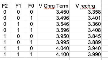
(This chart shows the wider spread reflected in the data sheet for when F2=0 and F1 = 1)
- ADC voltage error: +40-50mV (about 1.25%, which is acceptable)
- Booster efficiency with 4Ω load: 90% for VBAT = 4.1V, 77% for VBAT = 3.0V
- Input current limit on AC adapter: TBD.
- Fault thresholds on NTC pin: Cold = 75%, Hot = 34.6% (slightly low, but in spec).
Testing to date shows performance meeting specs, except for battery charging current, which is too high. The low currents from the battery indicate that it will be a long time between recharge events so expect long battery life.
Discussions
Become a Hackaday.io Member
Create an account to leave a comment. Already have an account? Log In.