 2-Zons
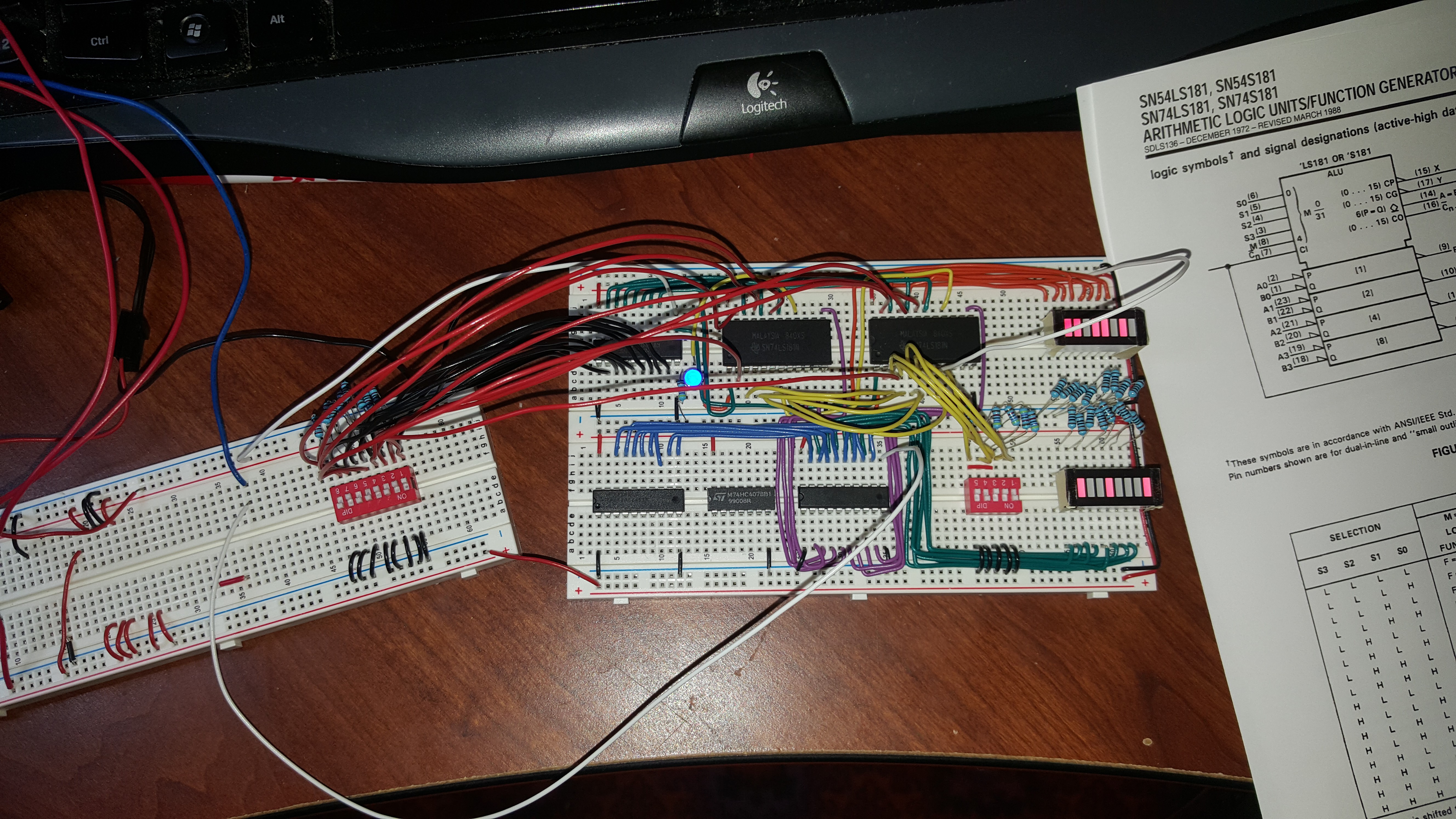
ALU is mostly complete and working. Using 2 x LS181's. Top right LED's show contents of input register tied to input B on 181's. Databus (Dipswitches) tied to input A. Blue LED is carry not. Bottom Right LED's show contents of output register. Showing A XOR B. All loopy wires are temporary for testing, as well as the 5 dipswitches on the board, they will be control signals when hooked up to the bus. Only need to implement zero, negative, and equal flags. I hope I can use the A=B output on the 181's and'ed but when I tested it in logisim it didn't work properly. I haven't tested on this setup yet.
Discussions
Become a Hackaday.io Member
Create an account to leave a comment. Already have an account? Log In.
nice work!
Are you sure? yes | no