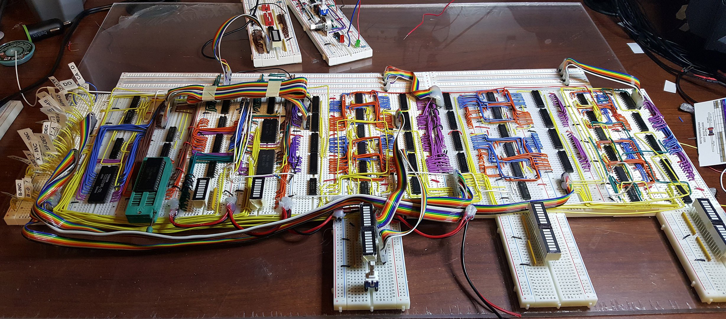
 Finished routing all the control signals to a single board. Need to build a few more ribbon cables for the address bus, data bus connections and LED's. Looks much neater now. Modules completed thus far (from left to right in picture): RAM / ROM module, ALU, XY register, stack pointer, and AB register.
No more loopy wires
A project log for 8 Bit Breadboard CPU
A home-brew 8 bit Microprocessor built on a breadboard 64K Address Space, IRQ, and DMA 16 Bit Stack Pointer, 4 8 bit Registers or 2 16 bit
 2-Zons
Discussions
Become a Hackaday.io Member
Create an account to leave a comment. Already have an account? Log In.
Good job taming the wiring beast! That looks really good. 8^)
Are you sure? yes | no
It looks very clean, but you need decoupling capacitors at every chip and possibly some electrolytic capacitors throughout the power rails. If you have an oscilloscope you should probe the 5V line all of the way at the end and I'm sure you'll see a significant amount of noise on the line as the computer clocks. This is the sort of thing that causes spurious problems as you add more chips or try to clock faster.
Are you sure? yes | no
looking really good! the organization and color coding looks fantastic!
Are you sure? yes | no
Thanks
Are you sure? yes | no