SCARA Model
Here is an example of the type of SCARA that I want to model:
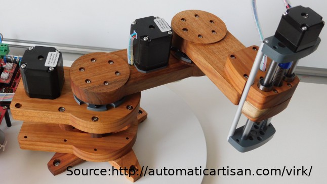
Two X and Y arms and linear Z (say):
L1 = 200mm
L2 = 150mm
Z = 150mm
Two stepper motors:
M1 = 400 steps (assume direct drive for the moment)
M2 = 400 steps(assume direct drive for the moment)
Also I want to use an Arduino Nano for the motion controller.
Forward Kinematics
Ignoring the Z axis for the time being, the forward kinematics represented by (U,V) to (X,Y), where (U,V) are polar motor steps and (X,Y) are the "real world" cartesian coordinates:
- U is the polar (angular) position (steps) for motor 1
- V is the polar (angular) position (steps) for motor 2
- X is the "x cartesian" position in mm
- Y is the "y cartesian" position in mm
The forward mathematics is:
- X=sin(2*Pi*U/M1)+sin(2*Pi*(U/M1+V/M2))
- Y=cos(2*Pi*U/M1)+cos(2*Pi*(U/M1+V/M2))
ReverseKinematics
Ignoring the Z axis for the time being, the reverse kinematics represented by (X,Y) to (U,V):
- R=sqrt(X*X+Y*Y)
- U=atan2(X,Y)-acos((L1*L1+R*R-L2*L2)/L1/R/2)
- V=PI-acos((L1*L1+L2*L2-R*R)/L1/L2/2)
or
- V=acos((R*R-L1*L1-L2*L2)/L1/L2/2)
I have reworked the equations to:
R=sqrt(X*X+Y*Y)
CosA=(L1*L1+R*R-L2*L2)
SinA=sqrt((2*L1*R-CosA)*(2*L1*R+CosA))
U=atan2(Y,X)-atan2(SinA,CosA)
CosA=(R*R-L1*L1-L2*L2)
SinA=sqrt((2*L1*L2-CosA)*(2*L1*L2+CosA))
V=atan2(SinA,CosA);
The reason is that sqrt() and atan2() is a well known for embedded applications.
Problems with Reverse Kinematics
Two issues:
- The equations assume either left or right elbow operation. The mathematics is right elbow at the moment.
- The cartesian coordinates do not map neatly with polar coordinates. That is, x and y positions do not usually match (map) an exact stepper motor position.
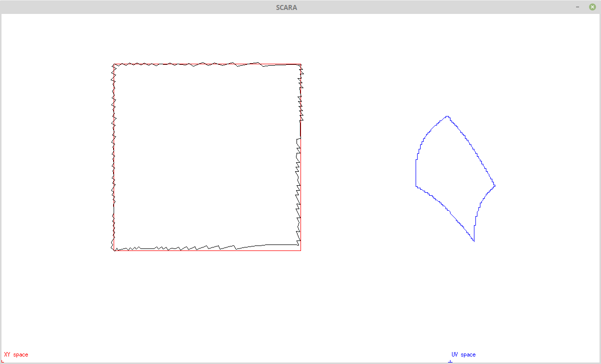
For example:
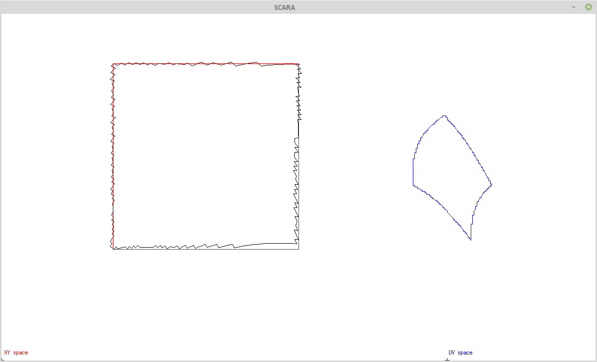
Note how straight lines in XY space are curves in UV space, and motor step resolution (in UV Space) maps into jagged steps in XY space.
(The plotted square is 125 mm x 125 mm, the arms are 200 mm and 150 mm, and the motors are both 400 steps.)
Okay, the third problem is the need for gearing as the motor step resolution is too low.
---
Mapping Options
I have tried three methods for accurate XY space to UV space.
Option 1
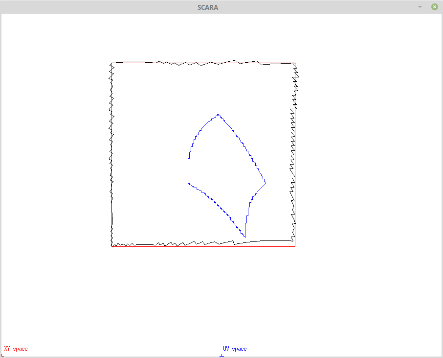
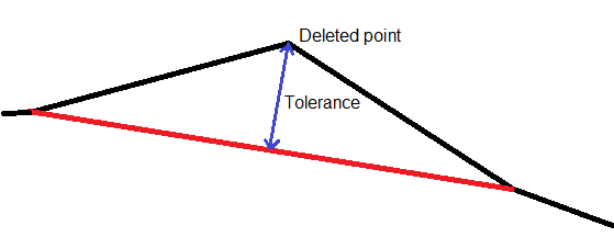
Segment the UV space curves into straight lines (by inserting points) using a tolerance (i.e. if the tolerance is not exceeded then a point need not be inserted):
This works well for feeding the mapped UV space directly into a Bressenham's Line Algorithm (i.e. Grbl).
This option could be pre-processing or on-the-fly (i.e. on the motion controller).
Option 2
Nearest UV space point mapping (path search):
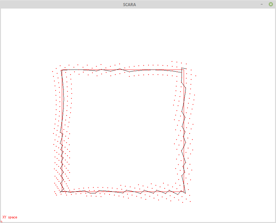
The method seems to be efficient (with look up tables) and path search algorithm can certainly be improved. This algorithm would replace the Bressenham's Line Algorithm (i.e. exports to the motor controller hardware directly).
This option would be on-the-fly (i.e. replaces Grbl).
Option 3
This options breaks the XY space lines into very small segments that are then mapped to UV Space. Duplicate UV space points can be removed. Simple but inefficient.
Pre-processing only.
AlanX
 agp.cooper
Discussions
Become a Hackaday.io Member
Create an account to leave a comment. Already have an account? Log In.