I repainted the bottom cover as I didn't like how my slots for the lights turned out. In the process of removing the paint, the polycarbonate got a haze on it that I never got rid of again. Polishing it would leave a coat of wax on it that I wouldn't be able to remove with what I have on hand, so I left it that way. I can come back to this later when I have more fresh polycarbonate to play with.

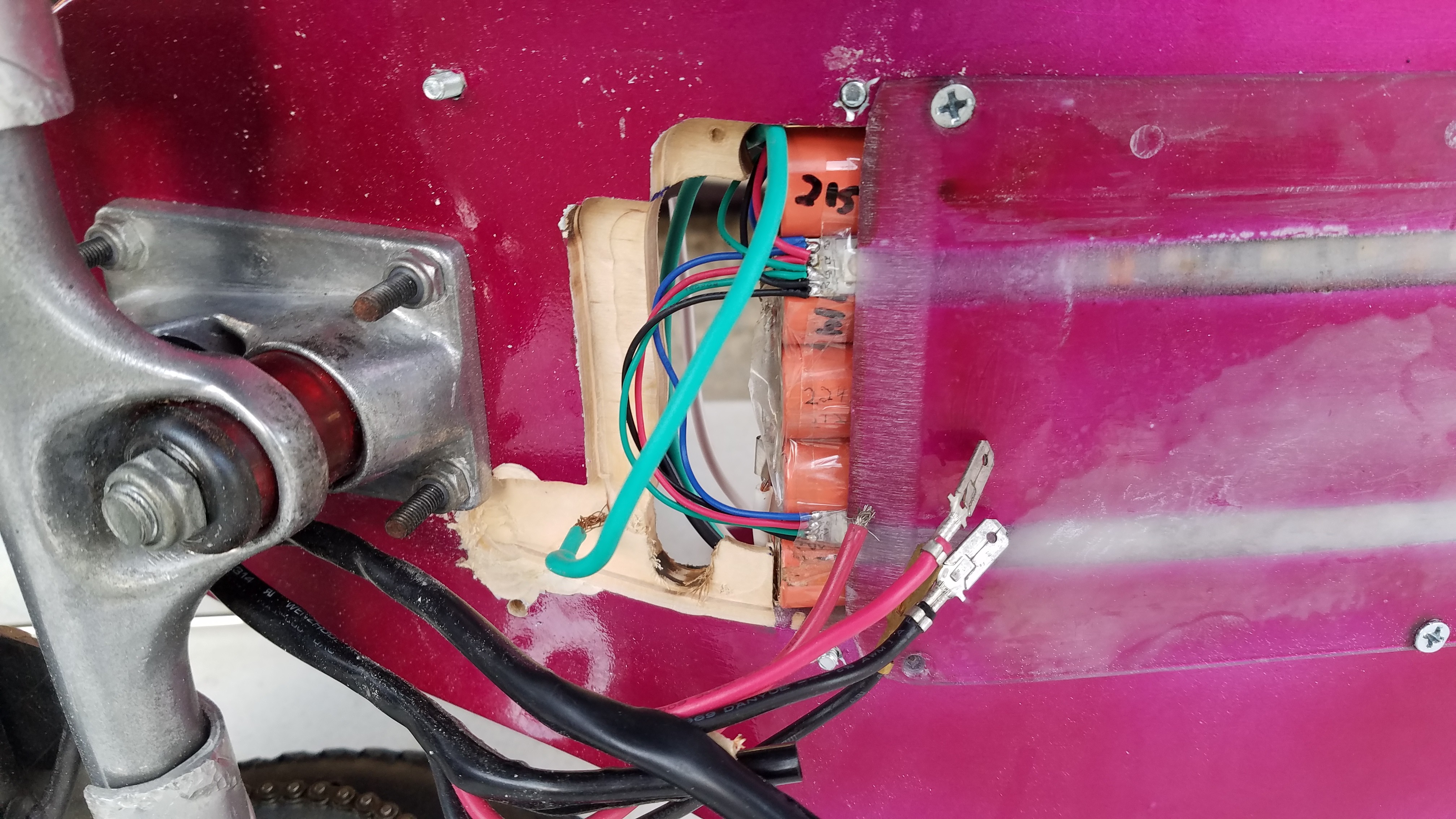
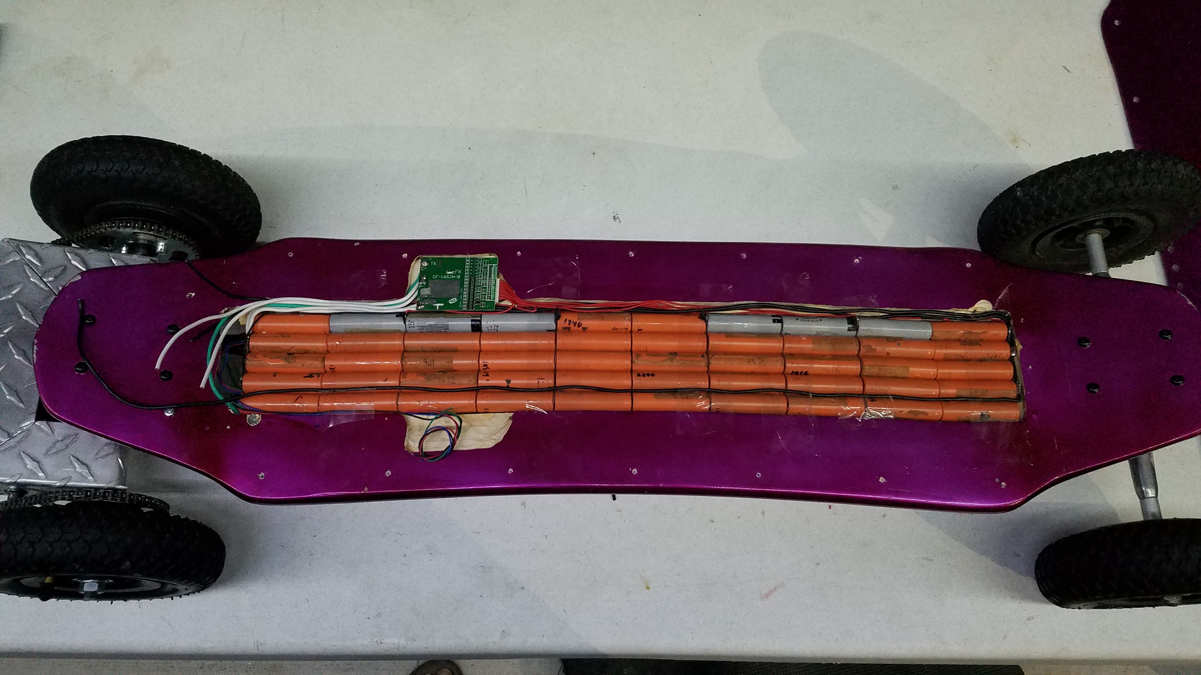
The battery was installed and wired up to the BMS. After some sparks flying and a close call touching an adjacent cell with the soldering iron tip, all of the balancing wires got a spacer of heat shrink tubing to protect the can of the lower cell from shorting to my folded nickel strips.

Power delivery is via two 12 gauge stranded wires in parallel which should allow me to draw 40A without heating. The 1.0C rating of these batteries is about 2500mAh, so for a 40A draw, that would put my 5 parallel cells discharging at 3.2C. That should be a pretty comfortable rate for them.

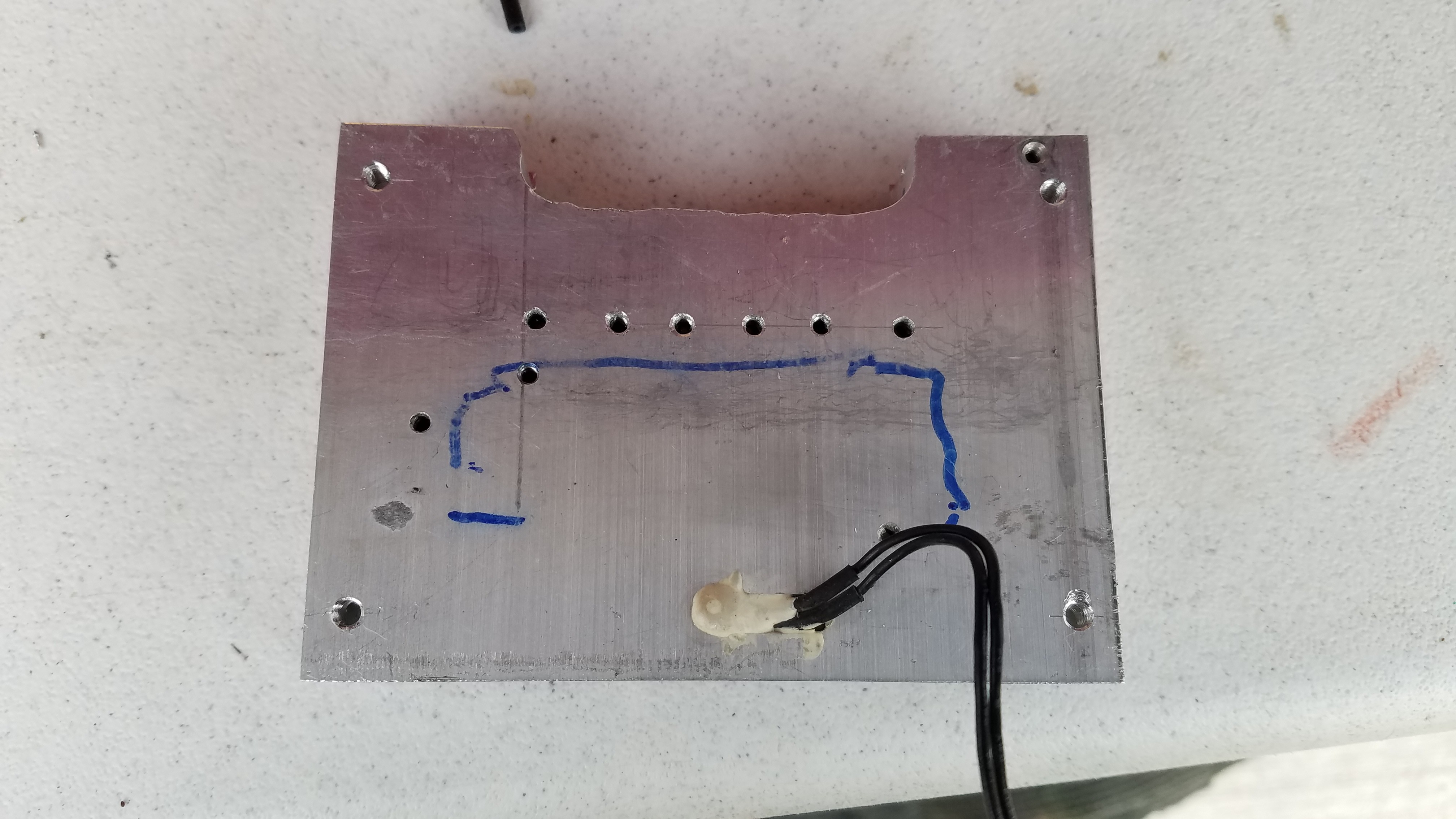
The heat sink got drilled and tapped with M4 screw holes in the corners for mounting, and M3 holes for the six mosfets which will be providing the motor control. This will give me independent control over each motor utilizing two N channel mosfets in parallel for forward, and one P channel (with an NPN transistor driving it) for braking. I've also included a pair of external schottky diodes to make coasting/passive braking regenerative. Active braking will just dump the power as heating of the motor windings, but I don't believe it will be used much anyway. The heatsink also got a slot cut with a wood router to make it fit better close up to the truck. That was really dangerous... and I would not recommend trying it.
 MasterOfNull
Discussions
Become a Hackaday.io Member
Create an account to leave a comment. Already have an account? Log In.