MasterOfNull
-
The weeds.
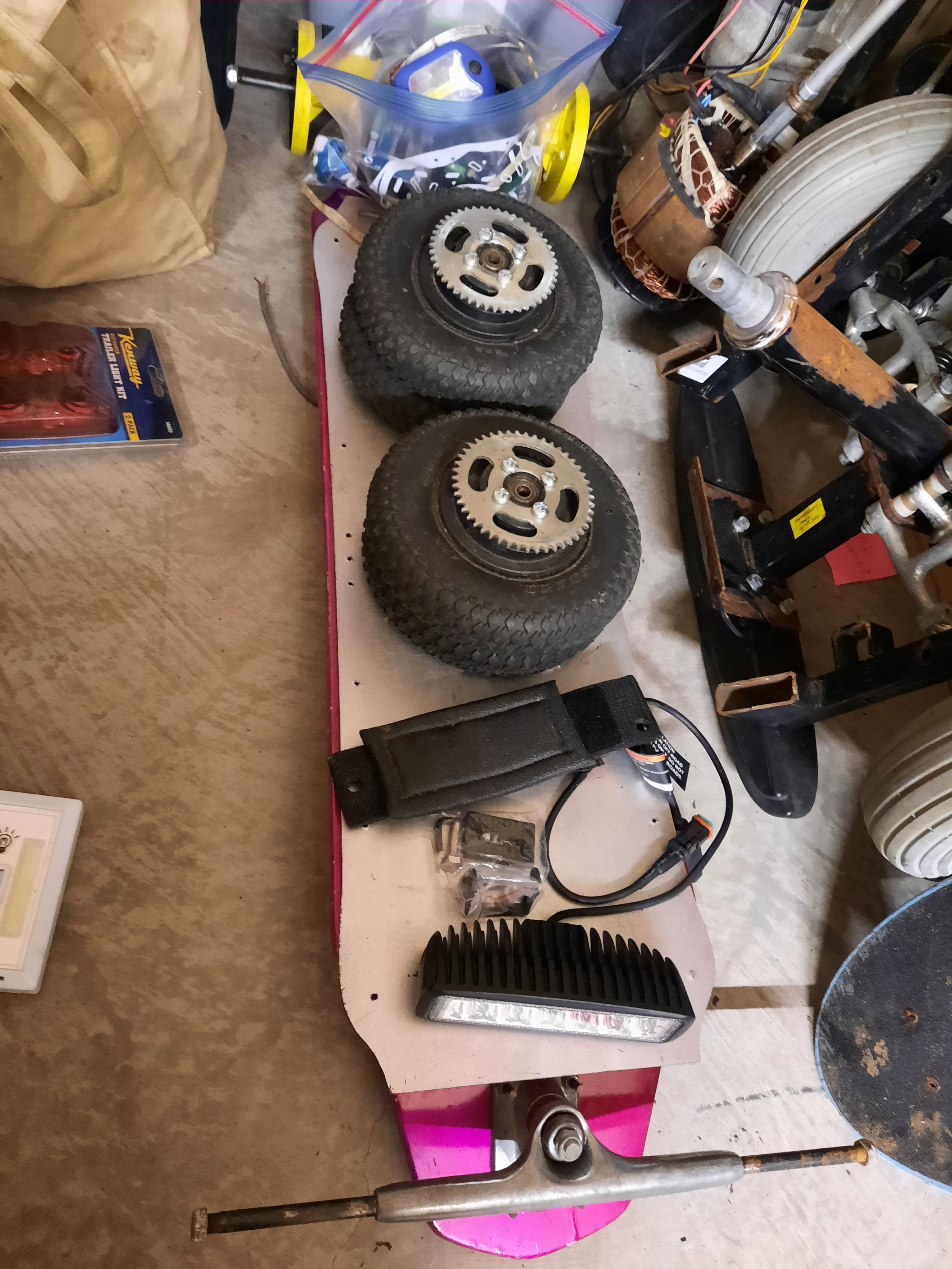
02/24/2022 at 02:42 • 0 commentsI have been off in them for a very long time. I am hoping to pick up a simplified and streamlined version of this soon. In the meantime here is my current pile of parts.
![]()
-
Moving advice
11/13/2019 at 06:17 • 0 commentsA while back while packing up to move, I had the brilliant idea of removing all the nozzles from my spray paint cans so I could move them without fearing that they would discharge without me present. I am a bit artsy on the side here, so I have a whole lot of partially consumed cans of spray paint/etc.
This worked great! Zero cans were erroneously discharged.
Just make sure to not misplace the bag full of nozzles during the move.
The stupid part is that I actually transported them in a steel filing cabinet where there was basically zero possibility of them being discharged.
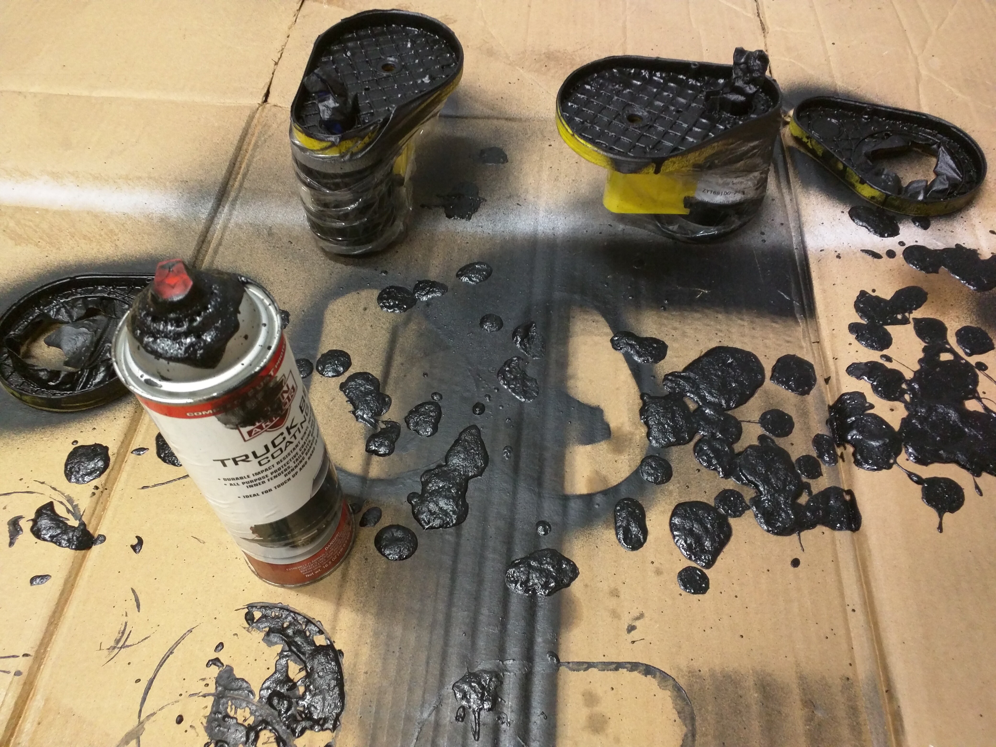
In any case, I decided that I was concerned about the noise the chain drive would make. So began a multi-step process for soundproofing them.
The actual soundproofing material contained acetone which would eat my ABS parts, so I protected my new chain covers with a coat of Plastidip first. Then I went to work coating with bedliner... without a properly fitting spary nozzle. Oof..
![]()
That is going to take a little while to dry.
-
Motor mount evolution.
11/07/2019 at 04:53 • 0 commentsI have high expectations as to how sturdy my 3D printed motor mounts will need to be. This was a task I originally had metal performing.
However, I think I have a good candidate here...
![]()
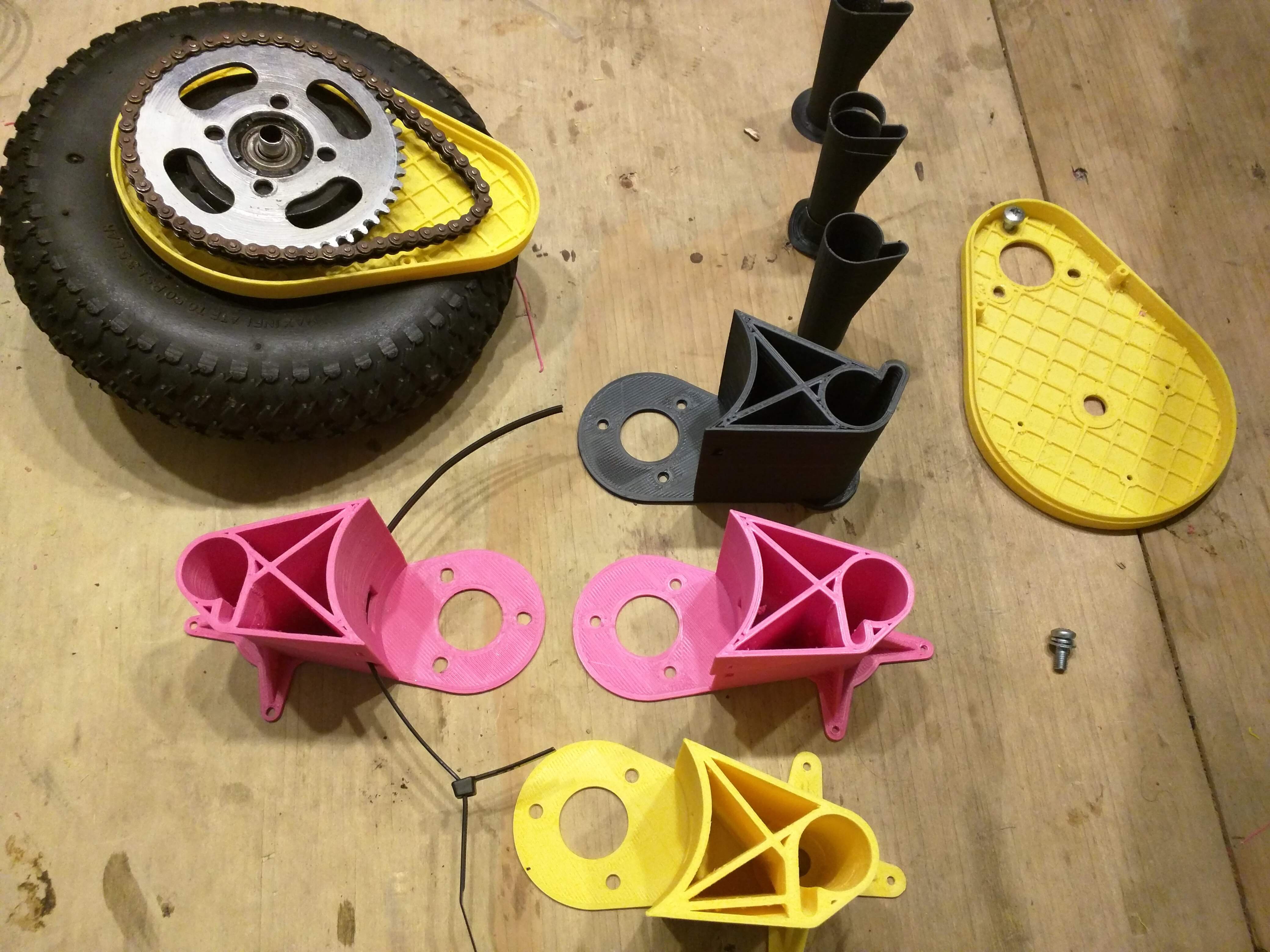
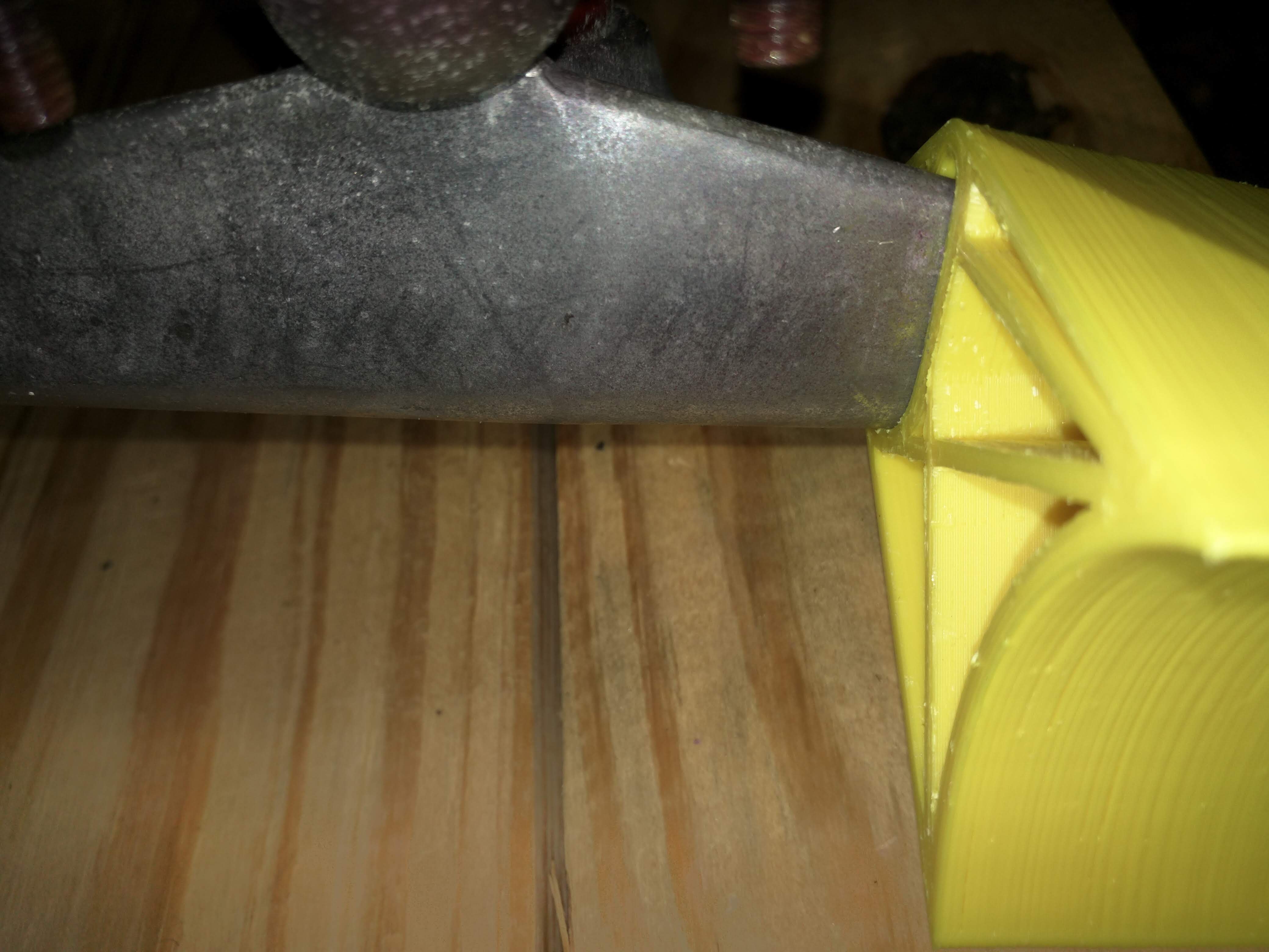
I printed a couple variations on the interface to the mountain board trucks, and then tested the winner by subjecting it to some substantial abuse.
![]()
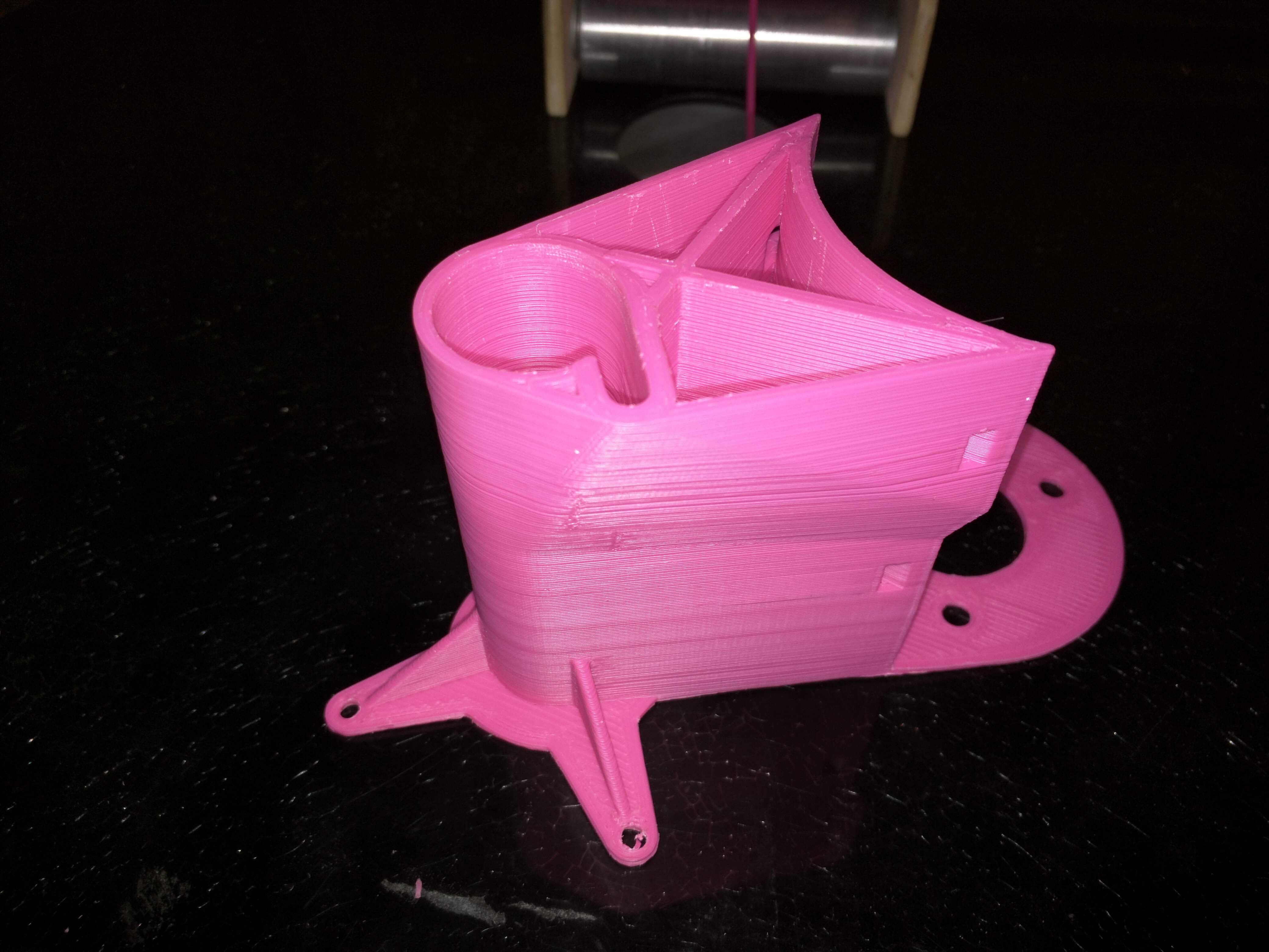
The bottom one in yellow ABS is the latest iteration.
My distance from the hub to the motor shaft was off by 0.5mm, my motor bolt pattern was off by 1mm, and the cover ended up being within 1mm of the chain.
So some destructive testing got to happen. :)
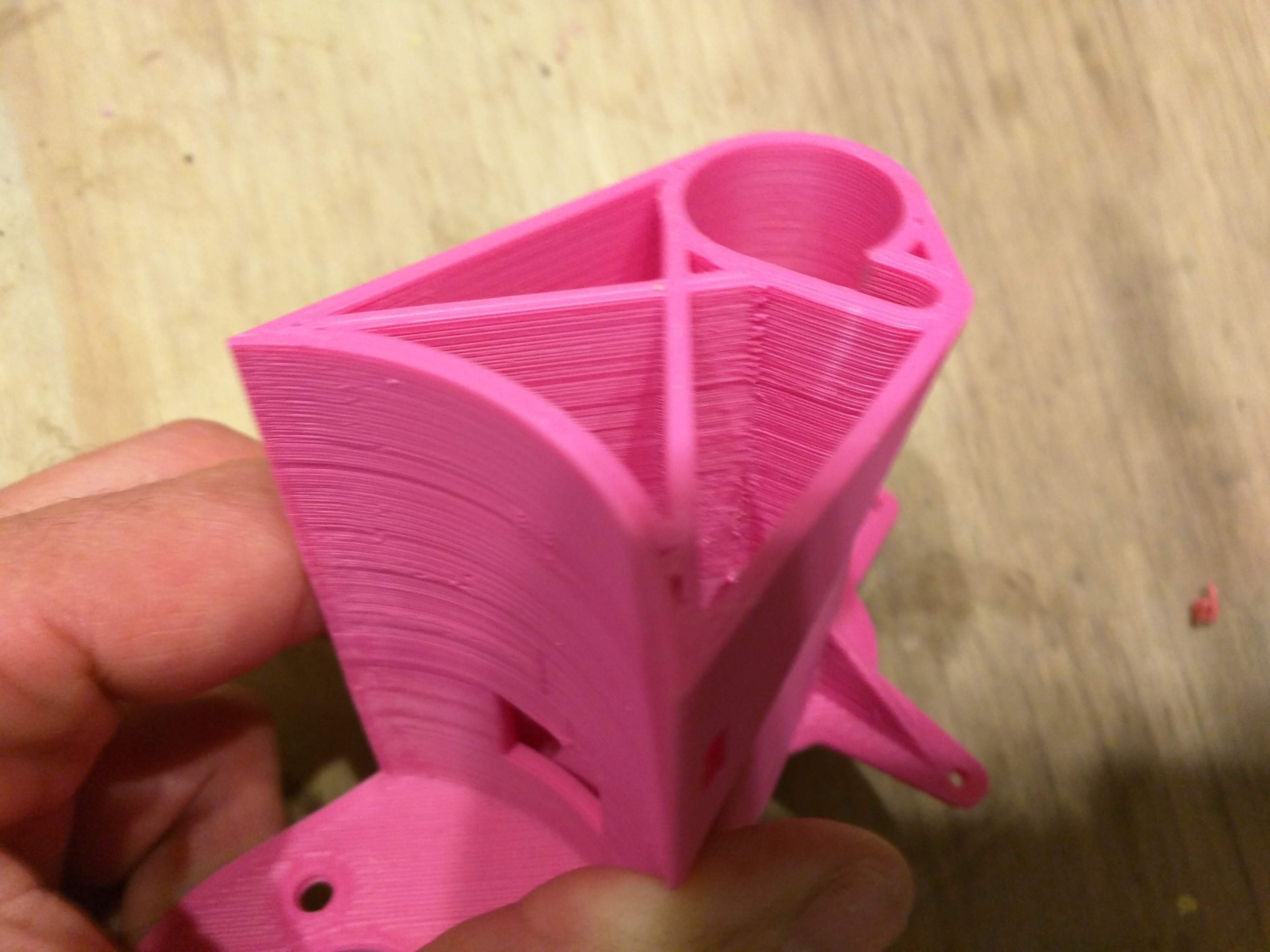
The previous version in pink did this when I subjected it to mounting it and then standing on the motor.
![]()
The little white line of discoloration on the side of the truck interface is what ABS does when it is under too much stress. I made that area thicker and added another cross-member.
![]()
I never really liked printing with ABS before, but now that I have my settings for it dialed in I'm much happier with it.
Layer adhesion was always a problem for me before with this when printing ABS. Printing it hot, fast, with a hot bed, and in a warm enclosure has solved all of my previous issues.
I'm sure I could still design a part that would pull itself off of the bed, but just a little planning seems to have sorted that.
Four more parts to go.
-
3D printed motor mounts
11/04/2019 at 23:53 • 0 commentsI got a little time to work on this last weekend, and so I modeled some covers for the chain drive. This became frustrating as my current AL motor mounts were made from diamond plate, and so the surface I needed to mate the cover to was decidedly uneven.
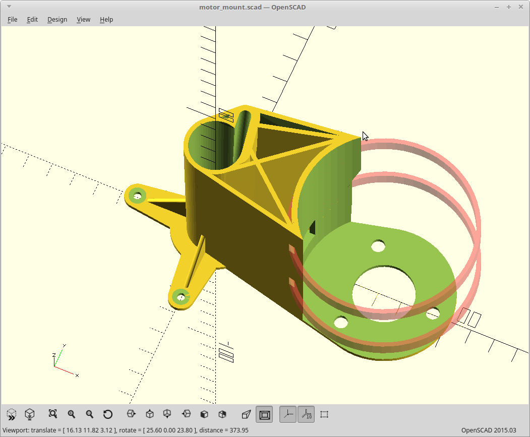
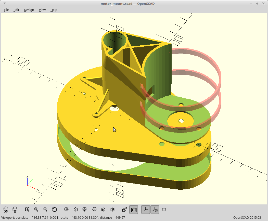
So.. some 3D printed motor mounts, happened. The up-front TL;DR image:
![]()
The red rings are where zipties go. This keeps the motor coupled to the shaft so that the mounting flange itself only needs to prevent rotation.
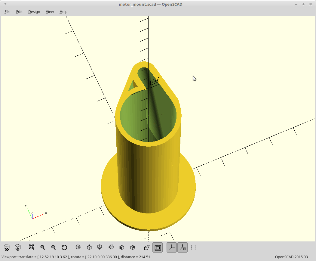
I needed to tightly fit the rib on the trucks to prevent rotation, so I modeled just that and printed it until I got the fit perfect. It only took 3 tries.
![]()
Once I had that done, I expanded the model to mount the motor the same distance from the hub as it is now.
At first I tried relocating the motors to in front of the wheels/underneath the board. Notice the forward position of the rib from the trucks here.
![]()
That didn't work so well. To still clear the board when turning the mounts had to be angled down towards the ground when positioned under the board. This compromised my ground clearance.
So I moved them back to where they were before: up and behind the rear trucks.
![]()
In the process here I did a bunch of test prints with various settings trying to get the strongest ABS parts I could using the least amount of material. That could and probably will be an entire log by itself but for now...
The best settings amounted to:
- Build surface: 110C
- Extruder: 280C
- +5% over-extrusion
- No cooling
- 0.6mm nozzle
- 3 walls, 8000 bottom layers (aka, print everything as a bottom layer)
- 45mm/sec for walls, 30mm/sec top/bottom
The 8000 bottom layers trick is how I print solid objects. It works better than actually using Infill: 100%.
Of course I got lost in the weeds here and so I still have yet to print the actual chain covers. :)
-
Rebuild...ded.
09/05/2019 at 07:11 • 0 commentsRebuilt the lot of it. Done. Worked.
Put it through its paces, wide open, stalled, brake.
Going from wide open, to stalled, to wide open caused the forward mosfets I tested to fail shorted.
However, I did something wrong which ultimately invalidates my test. I never hooked up the return path for the forward schottky diodes. As such the only return path for the 'power off' spikes went through the body diodes instead and they are not really fast enough to handle them.
I was debating if I should hook that return path up to the charging input on my BMS, power output on the BMS, or directly to battery - and bypass the BMS. I never decided.
Time to pack up here so I'll have to replace those mosfets in a day or two.
<EDIT>I believe my testing methodology itself was the source of my eating mosfets here!
If I'm right, my BMS is triggering when I stall the motors, and my test used the relative ground of the battery and not the BMS for the gate voltage.
So.. my gate voltage would go from a comfy 3.8v to a fatal -35v... if/when the BMS starts tripping as the BMS actually interrupts the ground when it trips.
The BMS isn't supposed to trip until 100A, but that is another issue.
Thanks to @Bharbour for his suggestions on the issues I've been having here. It's hard to help without a schematic or pretty much any measurements, but he gave it a shot.. :)
</EDIT>
-
I can't be trusted with a soldering iron
09/03/2019 at 07:22 • 2 commentsAfter a fun day with the family, this evening I went about replacing the under-rated transistors I had driving my braking mosfets with some BC337 ones. They have a more respectable 50v CE voltage rating and should work well.
I was offline and never bothered to check the datasheet for them. It's an NPN BJT transistor.. how hard can this be.
Cue the smell of atomized silicon and motors spinning out of control.
<insert expletives here>
Stupidly try the other channel...
<insert more expletives here>
Later, go read the actual datasheet. The 2N3904 has an EBC pinout. The BC337 has a CBE pinout. I built it with my transistors wired in backwards.
<insert even more expletives here>
I've now blown more power mosfets in the last week than I have in at least the last 5 years and I do terrible things with them. Then again, I usually don't just 'wing it' when the power involved could easily vaporize my wiring.
The main problem here is a combination of arrogance, the complete lack of much of my equipment, and the tiny form factor I've forced myself into. Keeping with my goal of fitting everything within the board cross section, the power section needs to fit in a rectangular cube 3/4x3/4x3in including connectors and the minimum space I need for the mosfets consumes most of that. So.. bench testing has been pretty much non-existent.
It works on paper. It physically fits. I just need to stop screwing up now.
I'll be rebuilding the power section again tomorrow. Good thing I keep a bin full of power mosfets and transistors around..
-
Fuse test mode
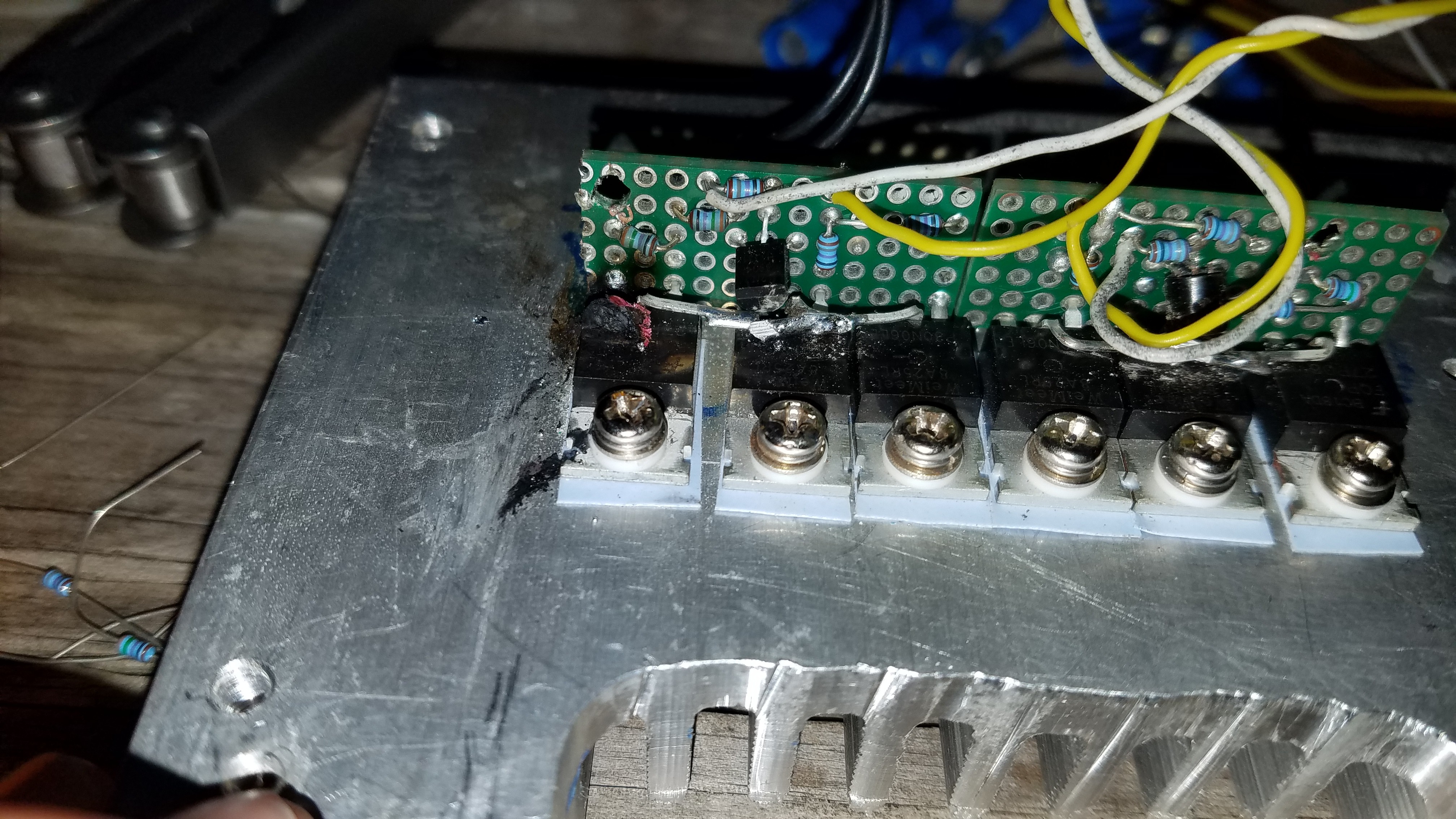
09/02/2019 at 06:00 • 3 commentsIt was all going so well. I tested forward and brake for both channels and it was working perfectly.
Then..
![]()
That is the magic smoke being released from the left braking mosfet. It was quite the event and I can tell you that mosfet never gave up.. it was positively glowing before I cut power. Perhaps I should have actually included the fuses in the test. :)
Somehow it seems to have taken the two drive mosfets with it during its demise. So it seems I will need to rebuild half of my board here to fix it. Ugh.
I have since discovered that the 2N3904 transistors I picked to drive my braking P channel mosfets have two different ratings online. One group is rated for 40v, the other for 60v. My battery voltage maxes out at 42v, so can only assume I have the cheaper ones. I am driving the P channel via a voltage divider to keep the gate voltage within the max Vgs of my mosfet here, so I'm basically left with that.
Currently rebuilding it with spade connectors, and seeing if I have some higher voltage rated NPN transistors here. Cross your fingers.
-
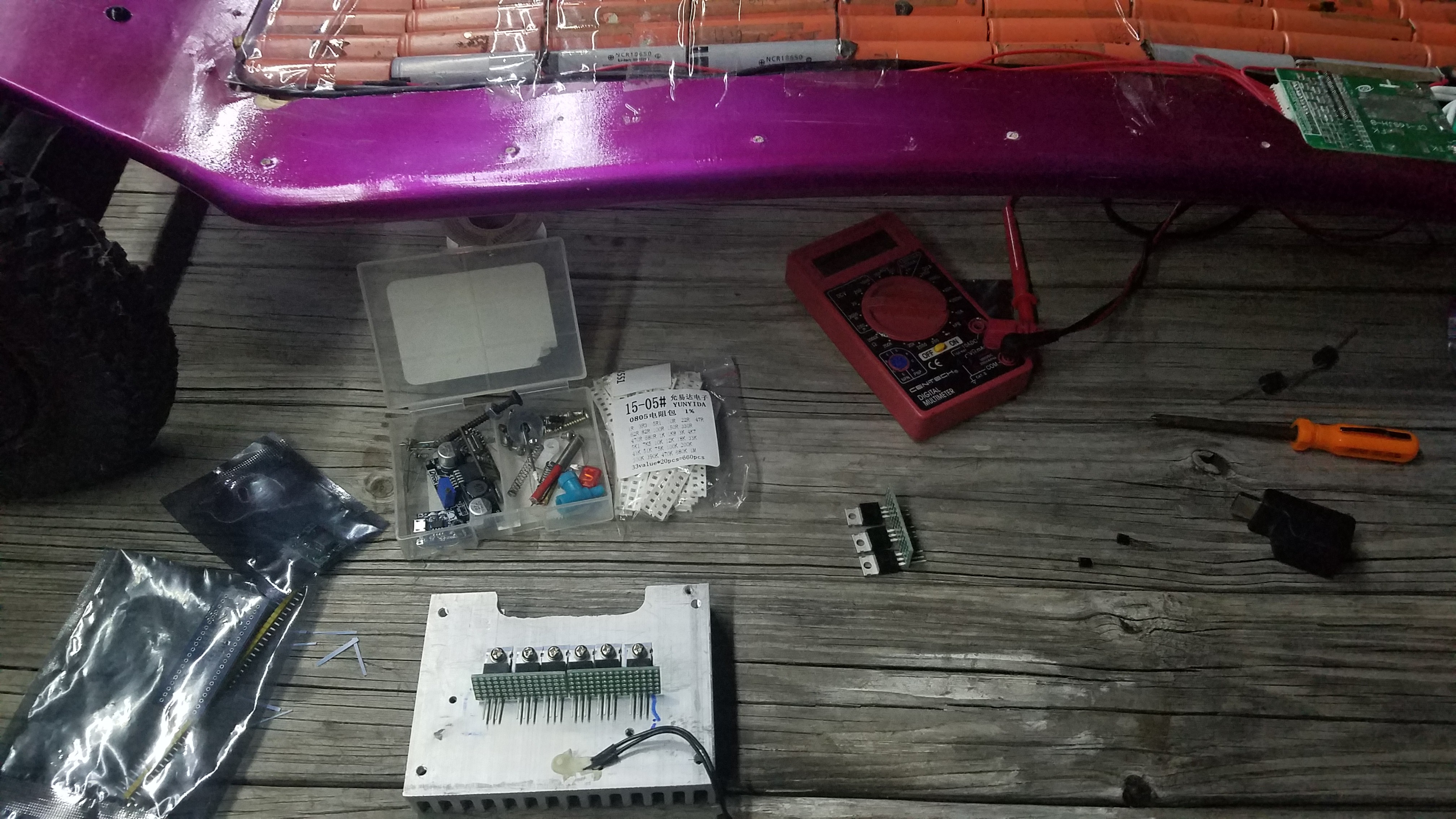
Electronics assembly
08/31/2019 at 02:22 • 0 comments![]()
![]()
Long weekend. Let's do this thing...
-
Regenerative half H bridges?
08/27/2019 at 04:19 • 5 commentsFor the motor control, I'll be using a half H bridge. I'm controlling each motor separately, so that's two of them.
A half H bridge will give me 'forward' PWM and 'braking' PWM.
Basically I'm using the circuit used in this article, with a capacitor across the supply, and an added schottky diode across the 'forward' PWM mosfet. I'll get to that bit in a moment...
I've been thinking about how I could implement regenerative braking.
The normal problem with implementing regenerative braking is that your motor voltage has to be higher than the supply voltage to actually put power back into the supply.
A DC motor will spin at a given RPM for a given voltage. To have a DC motor do regenerative braking would mean you would have to be going down a serious hill or switch in a boost convertor to raise the motor voltage above the supply voltage during braking.
Or... maybe not.
I've been toying with the idea of using the inductance of the motor itself as a DC-DC boost convertor. The idea works like this.
I'll short the motor with the braking mosfet, briefly. This will create a high current across the windings of the motor. The windings are basically a big inductor. When I stop shorting the windings that inductor current will still want to flow, and the voltage across it will spike. The motor is already connected to battery + and has a path back to battery - through the 'forward' power mosfet body diode. Add a decent sized capacitor across the supply rails to soak up and smooth out those spikes and... viola. Regenerative braking with one extra component, but it would suck.
The normal mosfet body diodes are slow to conduct, and have a voltage drop of 0.6-1.2v. So... I add a schottky diode in parallel to the normal body diode of the 'forward' mosfet. Schottky diodes are much faster to conduct, and only have a voltage drop of 0.2v.
There are a lot of questions I'll need to answer to make this work well though and there is going to need to be some experimentation. I'll need to see how fast the 'inductor' decays to time how often I need to short it, how fast and for how long I need to turn on the braking mosfet, will I still need to be applying power to keep the field up for the windings, how will commutation affect the inductance, and will my BMS even allow power to be fed back into it... to name a few.
The good news if it doesn't work at all, I'll still have power and braking with the same circuit :)
-
Welcome Morning.Star!
08/12/2019 at 17:21 • 0 commentsPlease welcome @Morning.Star to the project!
![]()
I gave him a basic framework of my thoughts on the lighting and control code and he is graciously going to lend a tentacle towards making it actually work.
I got all the libraries needed loaded for the remote on an Arduino mini, but there is not much room left for anything else. Wish him luck..
REMB - Raz0r Electric Mountain Board
An electric mountain board, built from scooter parts.