 Alexander
Standard requests to BMS in the form of a request for basic data, secondary voltage and names in the ASCII line are parsed in the file (from the manufacturer). I will not analyze them. Further, the deals with undocumented features in the form of reading / writing EEPROM.
Process of reading configs (EEPROM)
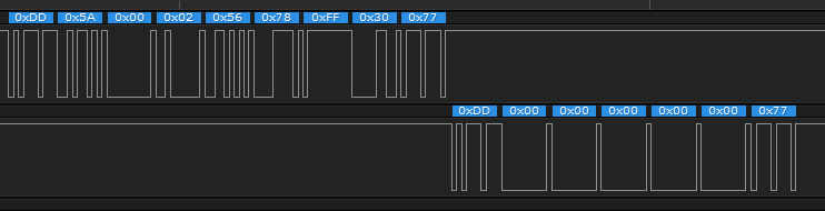
1. To switch to the EEPROM mode, you need to send the first packet to write to the zero register of the value: 0x56 0x78.
In response, zeros arrive (see figure below).
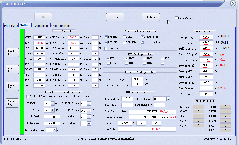
2. Then read (0xA5) registers from 0x10 to 0xA2 and 0xAA.
In figure below shown meaning registers (but I'm not sure about the accuracy of everything).
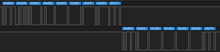
3. After reading, the write command to the register 0x01.
Without the start packet and the final, an error (0x80) is returned when the configuration registers are requested or changed.
Error counter
1 BMS stores in memory the fact of errors that can be configured in JBD Tools. It is useful to read them every time you start a device with BMS to analyze past events. After reading them, you need to pack them up so that next time you can only read actual events.
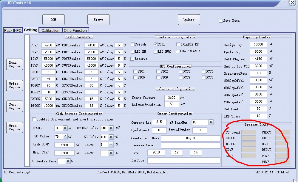
Reading is possible only in EEPROM reading mode (see step 1).
2 The command to read the register 0xDD 0xA5 0xAA 0x00 0xFF 0x56 0x77. Register that stores error counters 0xAA. The table below shows the meaning of each byte in sending a reply from BMS to the request 0xAA. High byte in front.
| Byte in the package | Meaning |
| 4-5 | SC count |
| 6-7 | CHGOC (Charge Over Current) |
| 8-9 | DSGOC (Discharge Over Current) |
| 10-11 | COVP (Cell Over Voltage Protection) |
| 12-13 | CUVP (Cell Under Voltage Protection) |
| 14-15 | CHGOT (Charge Over Temperature) |
| 16-17 | CHGUT (Charge Under Temperature) |
| 18-19 | DSGOT (Discharge Over Temperature) |
| 20-21 | DSGUT (Discharge Under Temperature) |
| 22-23 | POVP (Pack Over Voltage Protection) |
| 24-25 | PUVP (Pack Under Voltage Protection) |
3 Reset errors Error reset occurs by writing to configuration register 0x01. The package: 0xDD 0x5A, 0x01, 0x02, 0x28, 0x28, 0xFF, 0xAD, 0x77.
Discussions
Become a Hackaday.io Member
Create an account to leave a comment. Already have an account? Log In.