 spudfishScott
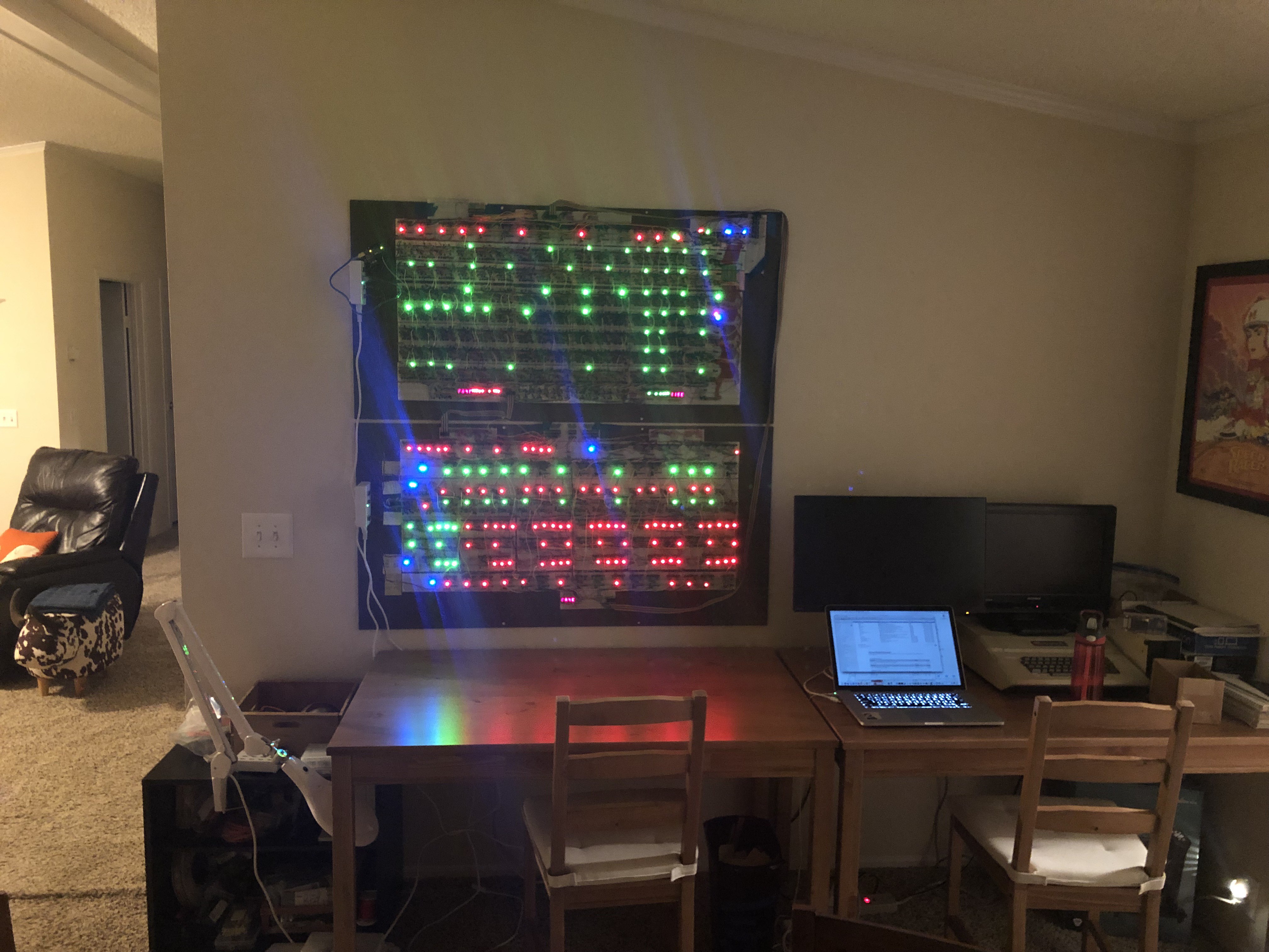
Two of the four major pegboards of the Spikeputor are now complete and have been mounted. They come down pretty easily in case repairs or modifications need to be made that can't be performed right on the wall.
Now that we have seven functioning registers and an ALU, we can put it through its paces by simulating the rest of the CPU. Wiring together the components along with an Arduino, the nascent CPU can be "programmed" by simply setting up the correct input signals after every rising clock pulse (also provided by the Arduino).

Since there is no RAM yet, the only storage is in the registers. Nevertheless, you can easily set up the Arduino to do something like this:
- Place the correct values in each of the registers:
- Select the register with Ra and Rc to output to Channel A and to allow the input to overwrite it (Rb is ignored)
- Turn Write Enable on
- Output the correct bit pattern to the CONSTANT input.
- Set ASEL to 0 (input from Register Channel A goes to ALU A)
- Set BSEL to 1 (input from CONSTANT goes to ALU B)
- Set the ALU to the ADDC function to add Input A to Input B.
- Rotate Left each of the registers:
- Select the register with Ra and Rc to output to Channel A and to allow the input to overwrite it (Rb is ignored)
- Turn Write Enable on
- Output 0x0001 to the CONSTANT input.
- Set ASEL to 0 (input from Register Channel A goes to ALU A)
- Set BSEL to 1 (input from CONSTANT goes to ALU B)
- Set the ALU to the Rotate Left function to rotate Input A by Input B bits.
- After doing this for all seven registers, pause briefly and loop back to another rotate cycle
And voilá! Ghost In The Machine!
You can also set up a similar type of loop, except instead of shifting bits, you can add a constant. This video starts with adding 1 by setting the ALU A Input DIP switch to 0x0001, outputting the selected register to Channel B with write-back, and cycling for a number of clock cycles before moving on to the next register. It shows the whole CPU, then focuses on the ALU output, and then Register Output Channel B. The DIP switch is then changed to 0x0010 to increment the second digit (by adding 16), leaving the first digit intact.
Finally, for something a bit more advanced, we can manipulate the control signals to simulate a program to calculate the first 24 Fibonacci numbers (all of them that can fit in 16 bits). After each number, the control signals are set to place the step number on RegMem Output Channel A and the corresponding Fibonacci number on RegMem Output Channel B, then pause before calculating the next one. The "program" uses four registers:
- R0 = N
- R 1 = Fib(N-2)
- R2 = Fib(N-1)
- R3 = Fib(N)
(Video in the dark for dramatic effect!)
Discussions
Become a Hackaday.io Member
Create an account to leave a comment. Already have an account? Log In.
wow, awesome!
Are you sure? yes | no
I guess you are using that Apple ][ as your main development station for that ultimate retro-feeling here ;-)
Are you sure? yes | no
Hah! But I WILL be using it for all of the I/O and mass storage. I'll be making an Apple peripheral card that will halt the Spikeputor CPU and access its memory directly.
Are you sure? yes | no
That looks awesome! Lots of blinky lights! 8^)
Are you sure? yes | no
Thanks! That’s pretty much the rationale for this project. Blinky lights with an artifact of computation.
Are you sure? yes | no