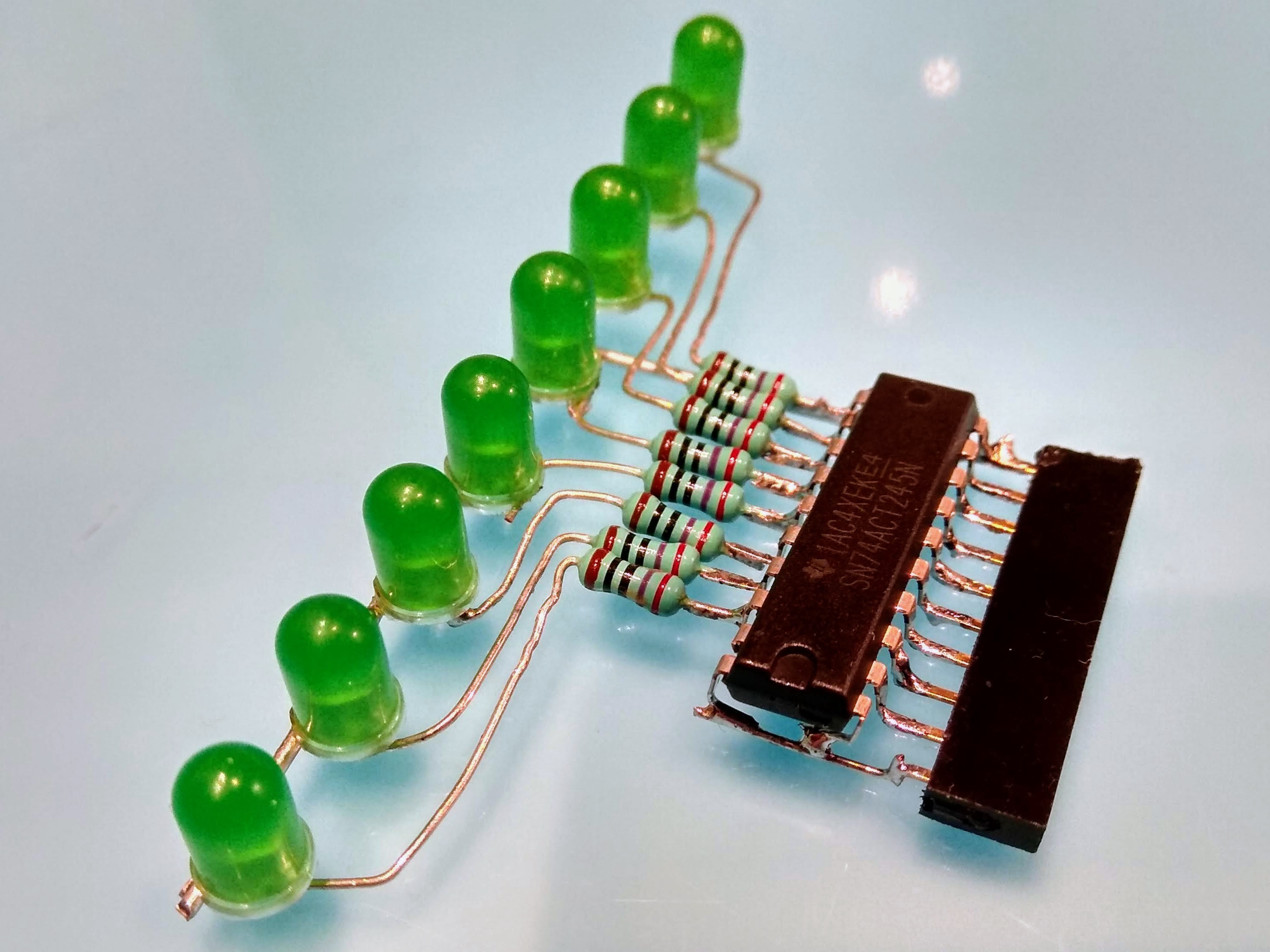
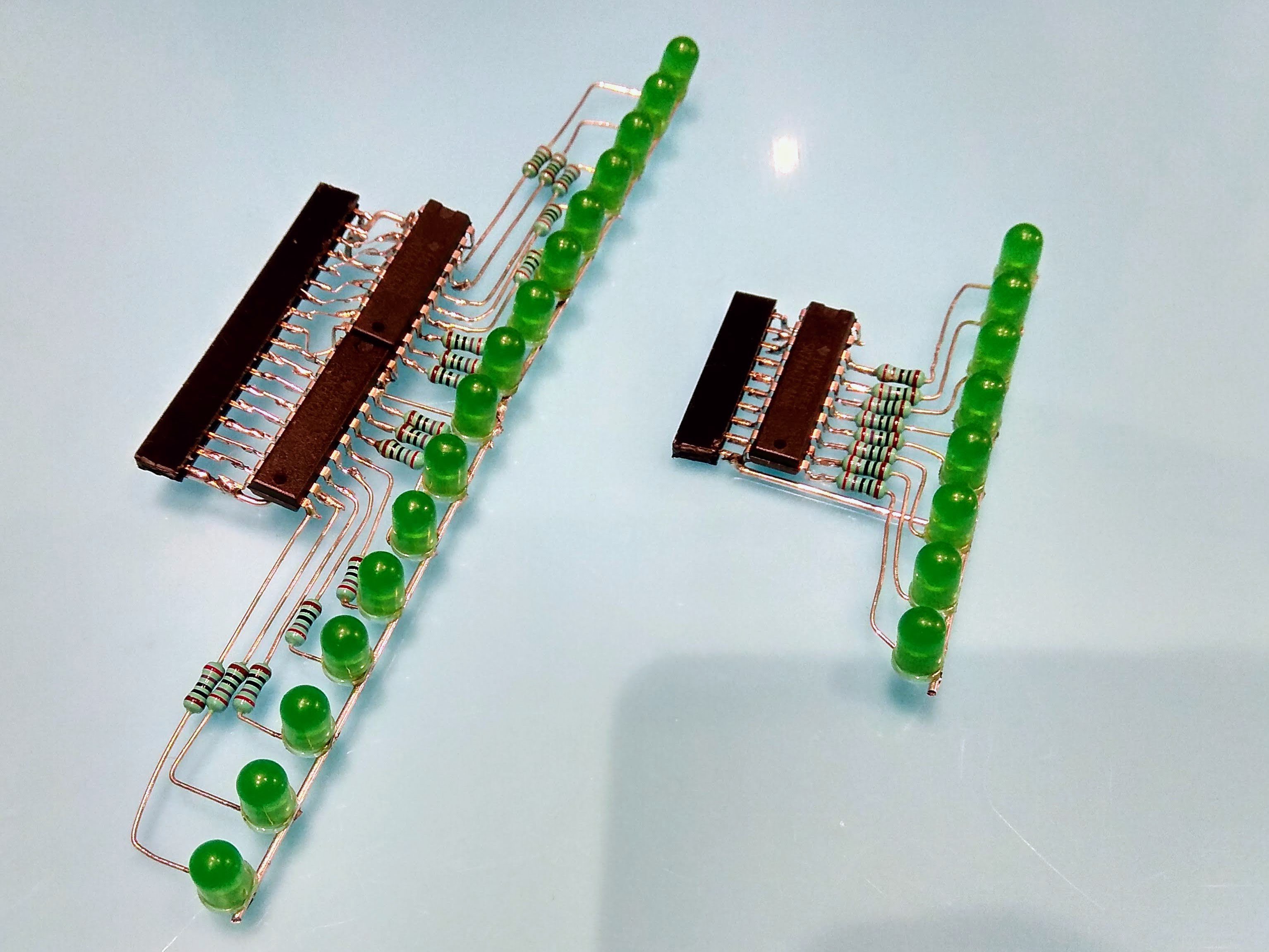
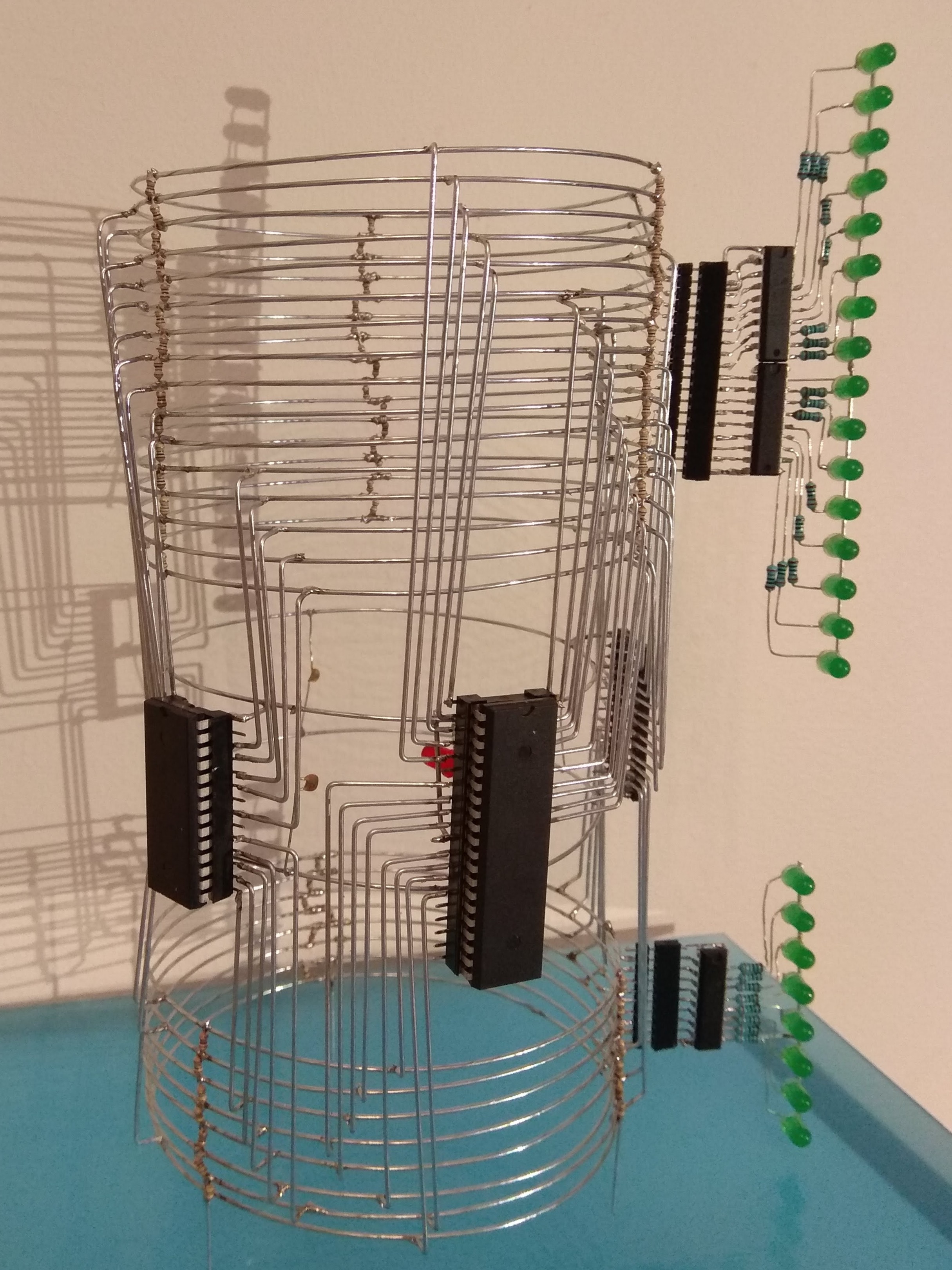
I decided to add some blinkenlights to the project so I tacked on a 10 pin header on the side of the databus rings (8 databits plus VCC/GND) and a 18 pin header on the side of the addresses rings.
For the databus I soldered up a female pinheaded directly to the inputs of a 74ACT245 octal transceiver and hooked up eight leds via resistors to it. Easy and straightforward soldering and looks not too shabby.
The addresses unit gave me a bit more grief. The A0..A7 from the pin header should be connected just straight over, but then there's the GND of the first '245 and pin 1 on the second that is not a part of the bus itself. So the connections between the second '245 and the pinheader is shifted two pins. And the spacing between the LEDs makes the routing of the resistors between the LEDs and the output of the '245s a bit awkward.
But I got it together in a semi-nice shape in the end at least.


 matseng
Discussions
Become a Hackaday.io Member
Create an account to leave a comment. Already have an account? Log In.