Solder the D-Sub connector(s) before soldering an IDC connector (2-row header), otherwise it will be much harder to solder the D-Sub(s).
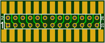
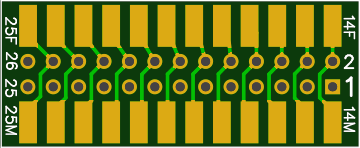
Be sure to understand the pin numbering. The industry-standard correlation has IDC26-1 going to DB25-1 but all other pins are not one-to-one. See pin numbering above or in the spreadsheet file. The PCB is labeled on both sides with the IDC/header pin numbers (1, 2, 25, 26). It is labeled on one side with D-Sub pin numbers with F for female connector and M for male connector. The IDC header needs to go on the top side of the PCB as shown below to get the proper pinout on a ribbon cable attached to the header.
Here is the top side of the PCB:
 And here is the bottom side:
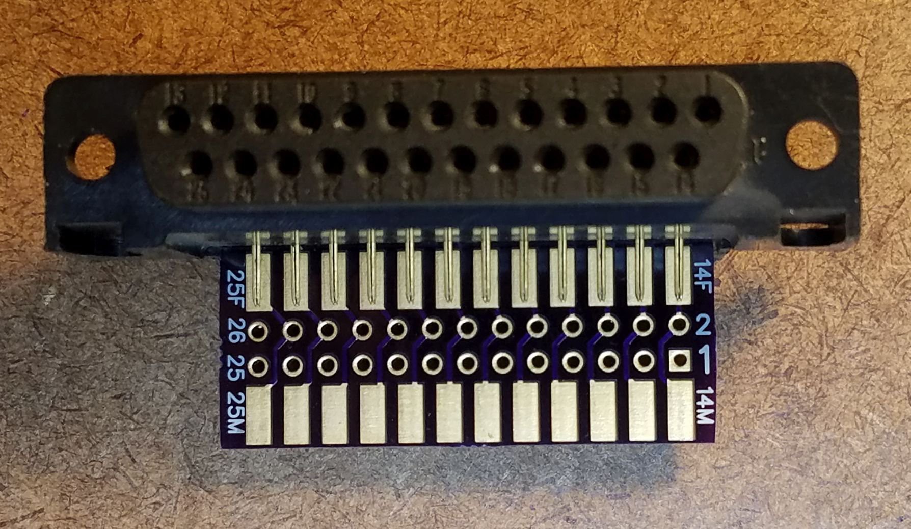
D-Sub connectors with pins (shown below) don't fit tight on the PCB unless the pins are bent inward. Bending the rows of pins inward is more-or-less a requirement for proper soldering.
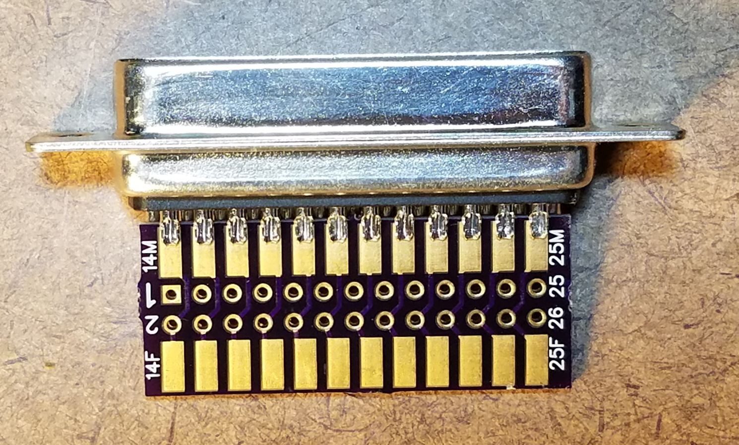
Solder-cup D-Sub connectors like this fit snugly.
Here is a board fully assembled with three connectors (sitting on the handle of a screwdriver).
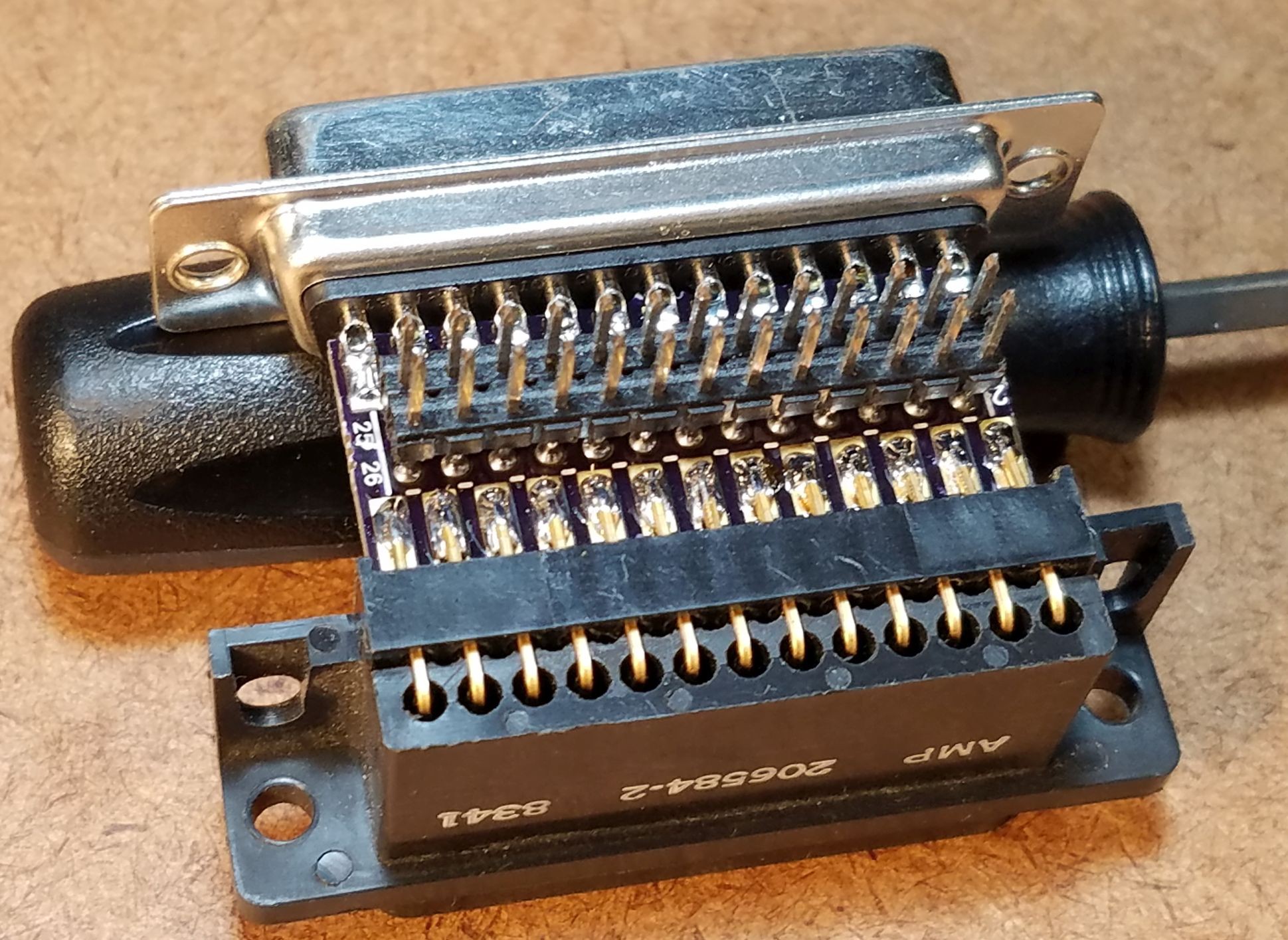 The PCB gerbers are available in the file section. The PCB is also available for ordering from OSH Park at https://oshpark.com/shared_projects/vJyVem1K