The flash needs to be externally mounted to keep the tracking mount as light as possible. Also, in a high pressure photo shoot, the flash should be powered externally. After Ken Rockwell extolled his frustrations with battery powered flashes https://www.kenrockwell.com/tech/strobes.htm, it behooved the lion kingdom to give the 580 EX II an extra boost.
The lion kingdom invested in a cheap JJC battery pack, for just the cost of a boost converter & a cable, only to find the JJC's are sold with 1 connector type for 1 camera. The goog reported the cables can't be bought separately.
https://www.amazon.com/JJC-BP-CA1-External-600EX-RT-YN600EX-RT/dp/B01GUNLQLW
So in its haste, the lion kingdom spent $18 on used a cable from fleebay which ended up broken.
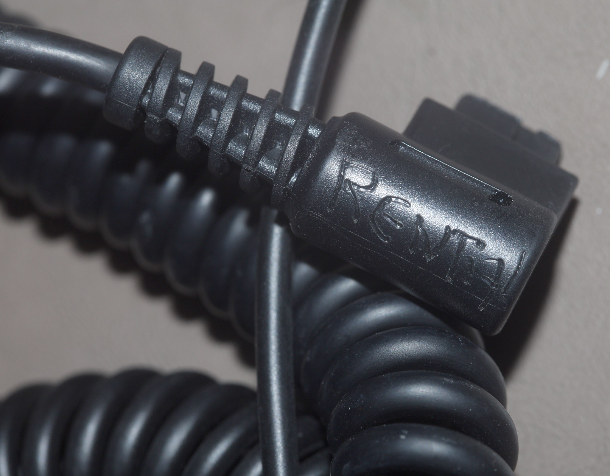
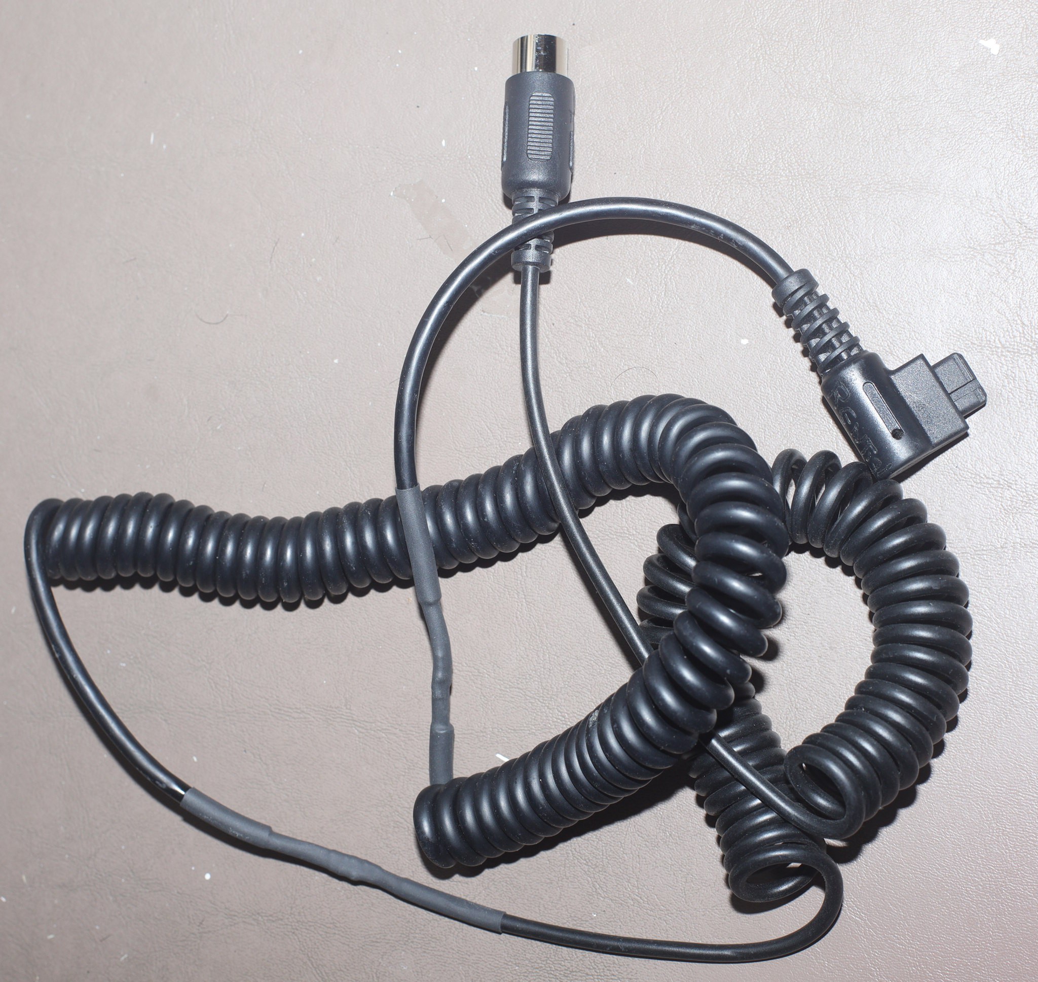
In the meantime, the goog updated its search results 5 days later to yield a brand new $12 cable.
https://www.amazon.com/Connecting-Replacement-JJC-Recycling-YN600EX-RT/dp/B01G8PMZ12
The total cost of the 1 hung lo JJC ended up more than a high end battery pack, not unlike how bang good soldering irons end up costing as much as a JBC with all the accessories. It wasn't the 1st time lions were ripped off by the fact that goog can take 5 days to perform a novel search.
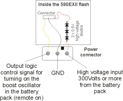
Since 2011, a drawing has circulated around the internet with the 580 EX II pinout, but nothing useful on the voltages. Fortunately, there actually is a servicing manual for the flash.
https://www.manualslib.com/download/379083/Canon-580exii.html
The control signal is 0-5V with 5V being the on signal.
The external battery pack directly feeds the mane capacitor through some diodes. The mane capacitor normally charges to 330V (page 24) but the status LED turns green when it's 213V & red when it's 268V (page 25). The flash MCU resets if the voltage goes above 350V. The external battery pack boosts what the internal charger already does, but doesn't have to completely charge the capacitor.
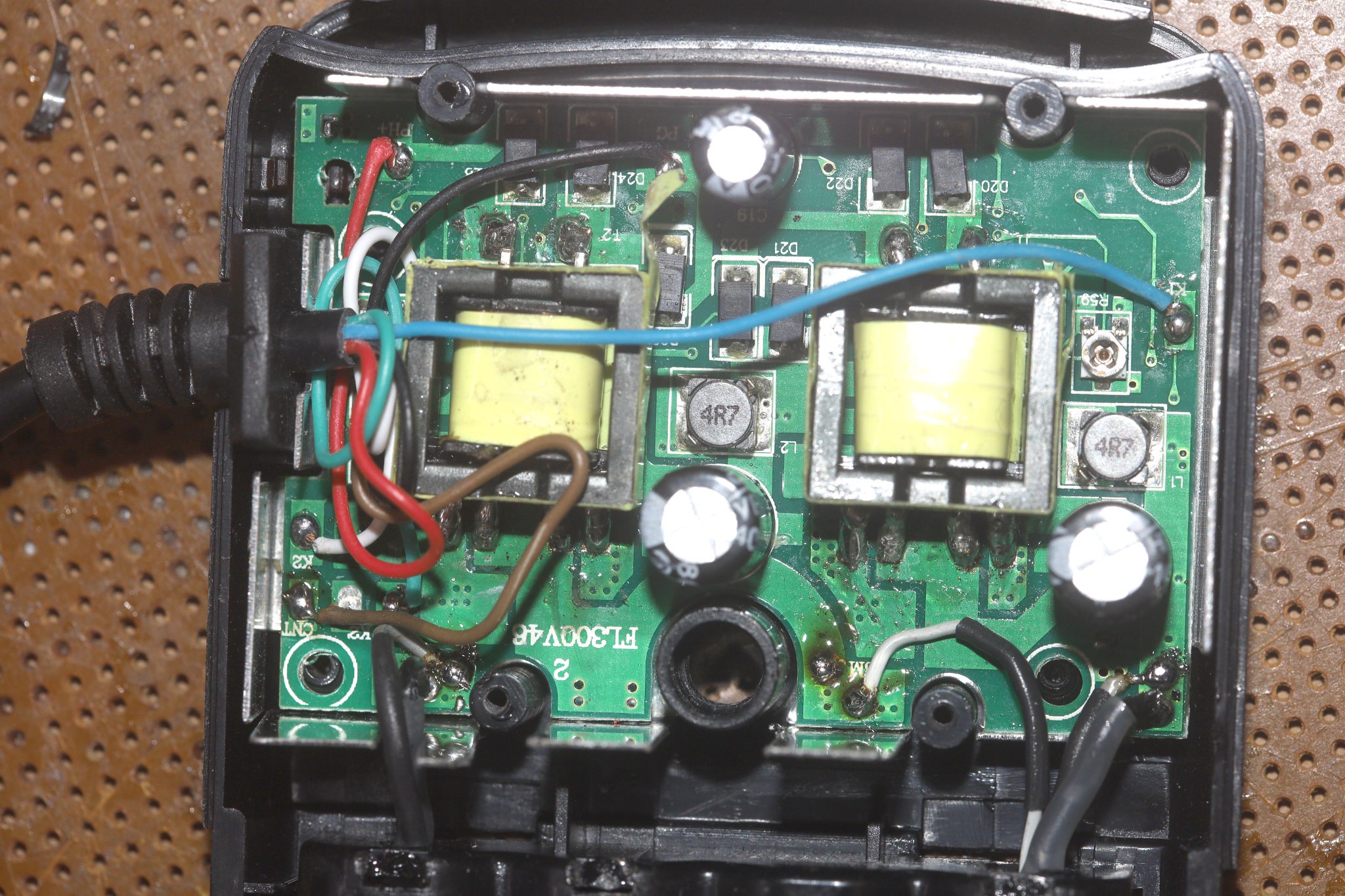
Interior after modifications to use a LIPO. Manely, the 3 battery terminals have been replaced.
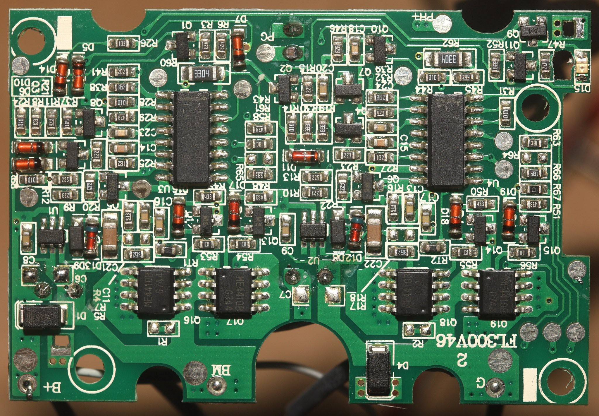
Turning to the JJC battery pack, the Nikon cable has a 100k resistor from K1' to K & a 100k resistor from GND to K2. PH+ is the high voltage. The resistors are probably selecting the voltage. CNT is the control signal from the flash.
The Canon cable has no resistors. All the K pins are floating. Only PH+, GND, & CNT are connected.
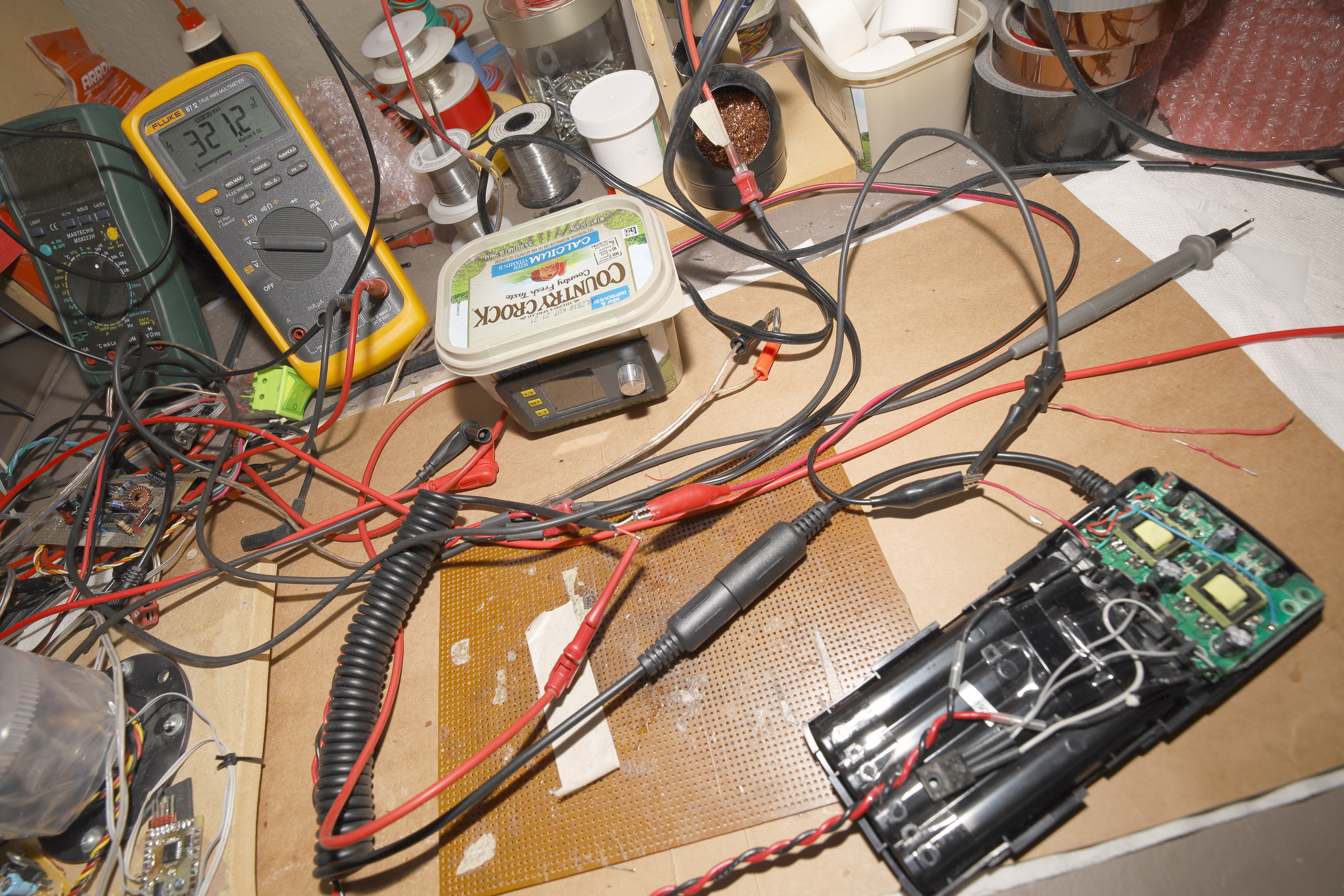
A quick test with the Nikon resistors showed it makes an unstable 290-320 volts.
All the external battery packs use 2 boost converters in parallel. Each boost converter runs on 6V. If they have 8 AA's, they run both boost converters. If they have 4 AA's, they run 1 boost converter.
The battery pack has 3 taps: 12V at B+, 6V at BM, GND at G. It can run on 6V from B+ to BM, or 6V from BM to G. To run it on a 12V lipo from B+ to G, a regulator has to supply the 6V tap to get both boost converters to fire. The lion kingdom whacked on an LM7806.
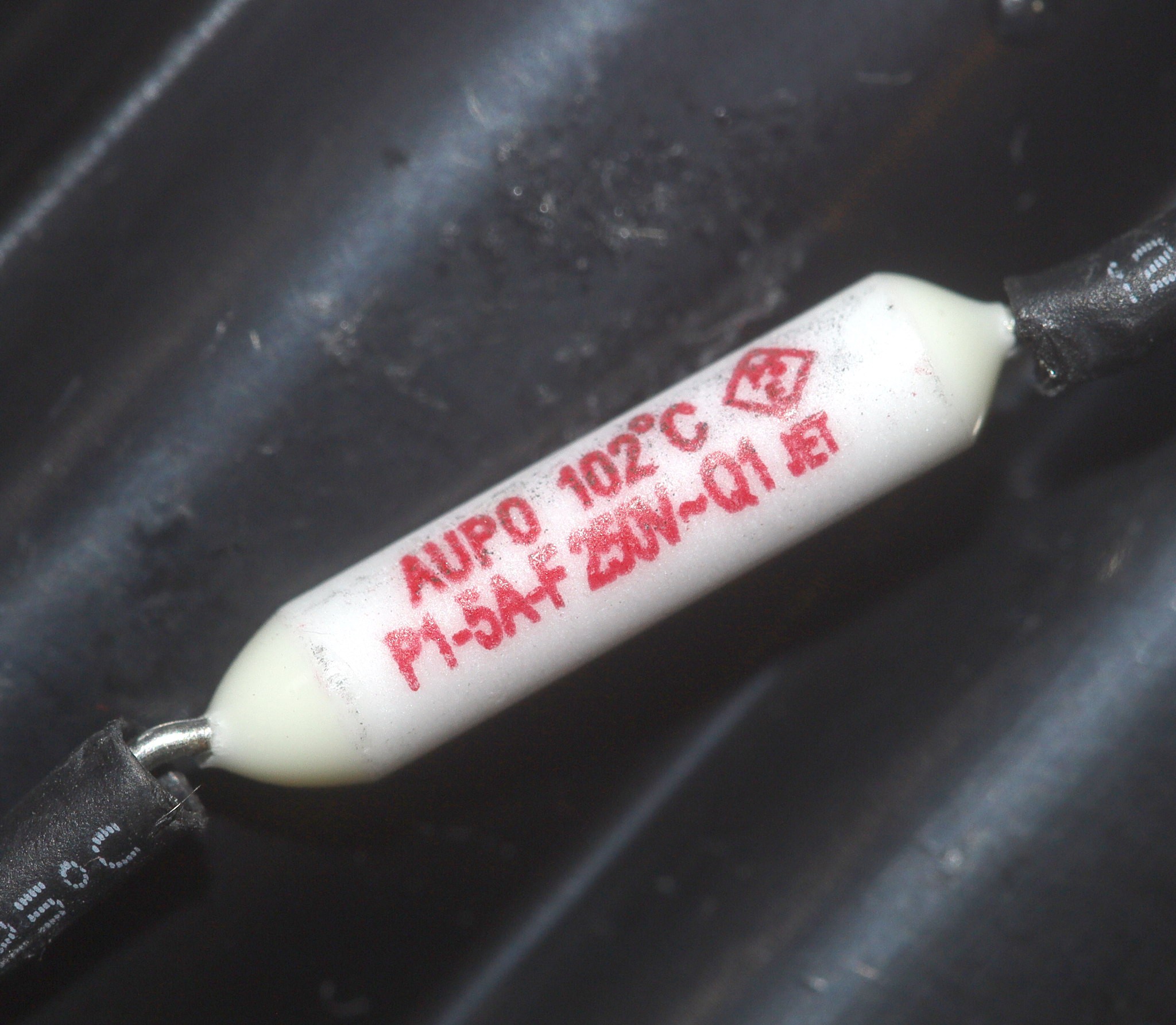
The JJC has 2 5A current limiting fuses going to the batteries. It's essential to leave these in place with their heatsinks.
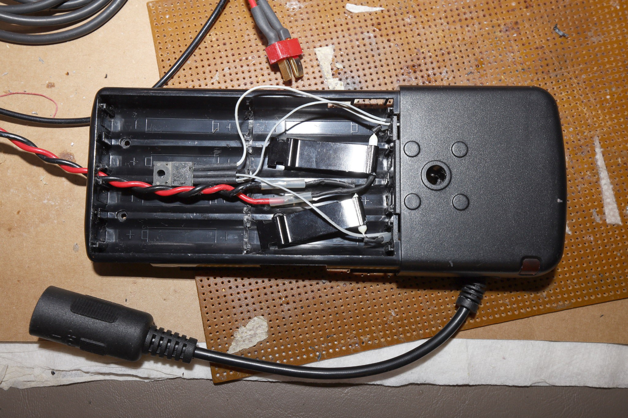
The JJC was modified with the 6V regulator & current limiting fuses in the battery compartment. In testing, the JJC drew 5A to charge the flash. Combined with the fresh batteries in the flash, it supplied more power than the flash could use without destroying itself. Running on a lipo, the 580 EX II is basically a very expensive manes powered strobe.
The 6V regulator got momentarily hot, but the flash couldn't draw enough power to keep it hot. It was time to see if it did anything useful.
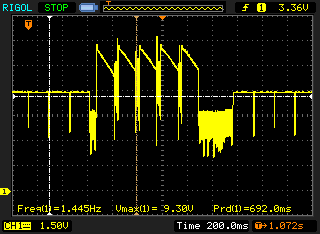
BM with the LM7806 when recharging
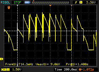
BM without the LM7806 when recharging.
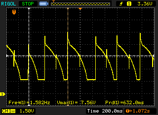
BM without the LM7806 when idle.
It's peak current is 2A while the boost converters are running 5A in series. It's obviously making a prettier waveform when idle but doing nothing when its recharging. BM is equally messy, so the LM7806 can be considered optional. The 2 boost converters just run in series when it's recharging.
 lion mclionhead
Discussions
Become a Hackaday.io Member
Create an account to leave a comment. Already have an account? Log In.