 Amos
AmosWell I couldn't leave it alone, so I started working on the data bus wiring and ALU this afternoon/evening. A few dabs of superglue has made the breadboard structure nice and secure and the data bus is now looking a bit neater without all the jumper wires everywhere.
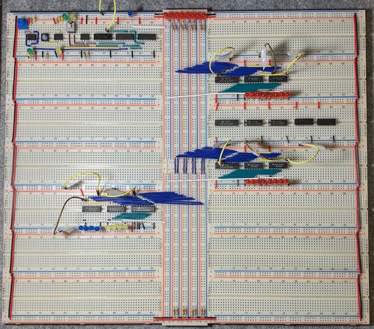
Due to the layout of the breadboards I am using, most of the data bus connections are slanted, but that's the best I could do. I am increasingly frustrated at the five holes then a gap in standard breadboard power rails - why don't they have tie points all the way along the power rails?
After doing the bus wiring, I started on the ALU - what a mess of wiring! I really can't see any other way and I admire Ben's efforts to try to keep the wiring as tidy as possible, but it really is messy. I only have the A register wired up so far, but a quick test shows that it is working, with no swapped bits.
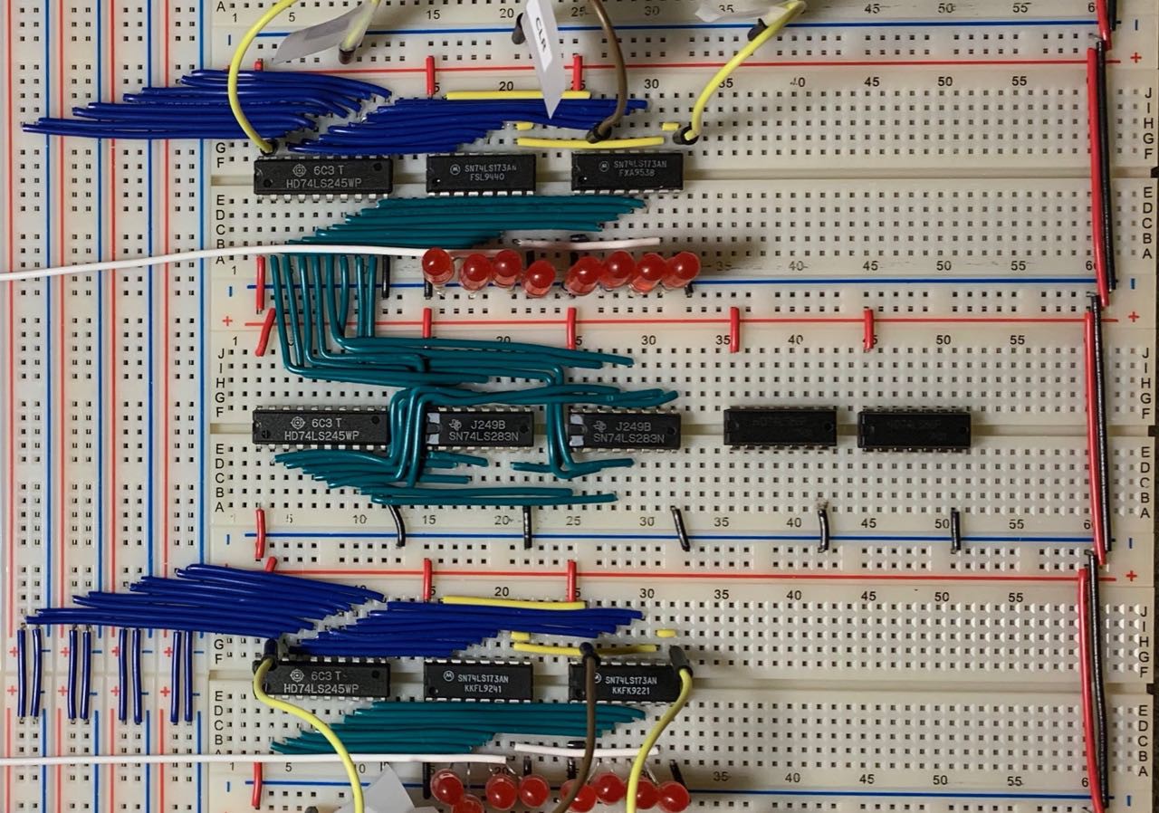
I have been half-thinking about committing this design to a PCB layout when I am finished and I think routing the ALU section is going to be a pain! When I get the B register wired in and tested I think that should be the worst of the wiring mess completed. The output and microcode modules are a bit cramped in places, but they don't seem as bad as the ALU is.
Discussions
Become a Hackaday.io Member
Create an account to leave a comment. Already have an account? Log In.