 Amos
AmosOkay, today I didn't do as much as I had hoped, but I am happy with what I did get done. A simple fix was wiring in a "clock bus" next to the data bus. This doesn't really add much to the project right now, but it should make routing the clock signal a bit neater as more of the computer gets built.
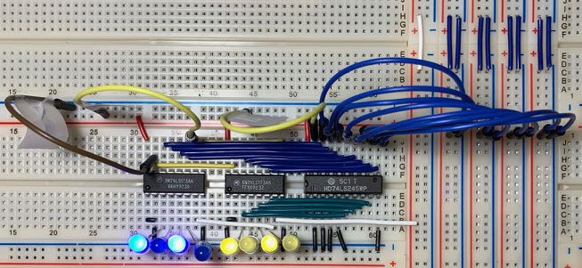
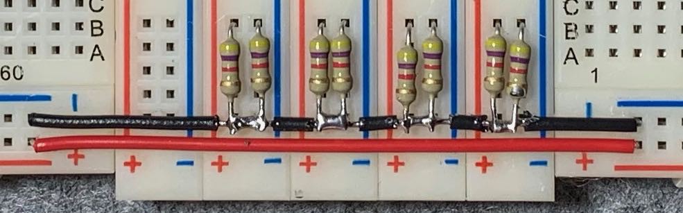
Then I added some pull-down resistors to the data bus. I spent too much time trying to get the resistors neatly positioned and soldering them to a negative rail. The soldering isn't my best work, but it will do for now - I can tidy it up later.
Finally, I added some indicator LEDs to the data bus. Again I spent too much time trying to get everything lined up nicely, but the end result isn't too bad IMHO.

I'll tackle the A and B registers next...
Discussions
Become a Hackaday.io Member
Create an account to leave a comment. Already have an account? Log In.