There is a kind of running gag in comments on hackaday blog. It goes like this, someone present a project using a MCU and a commenter says let's do it with a 555.
Usually one use a MCU to fade a LED. I say, let's do it with 555 timer.
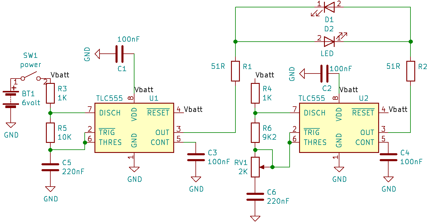
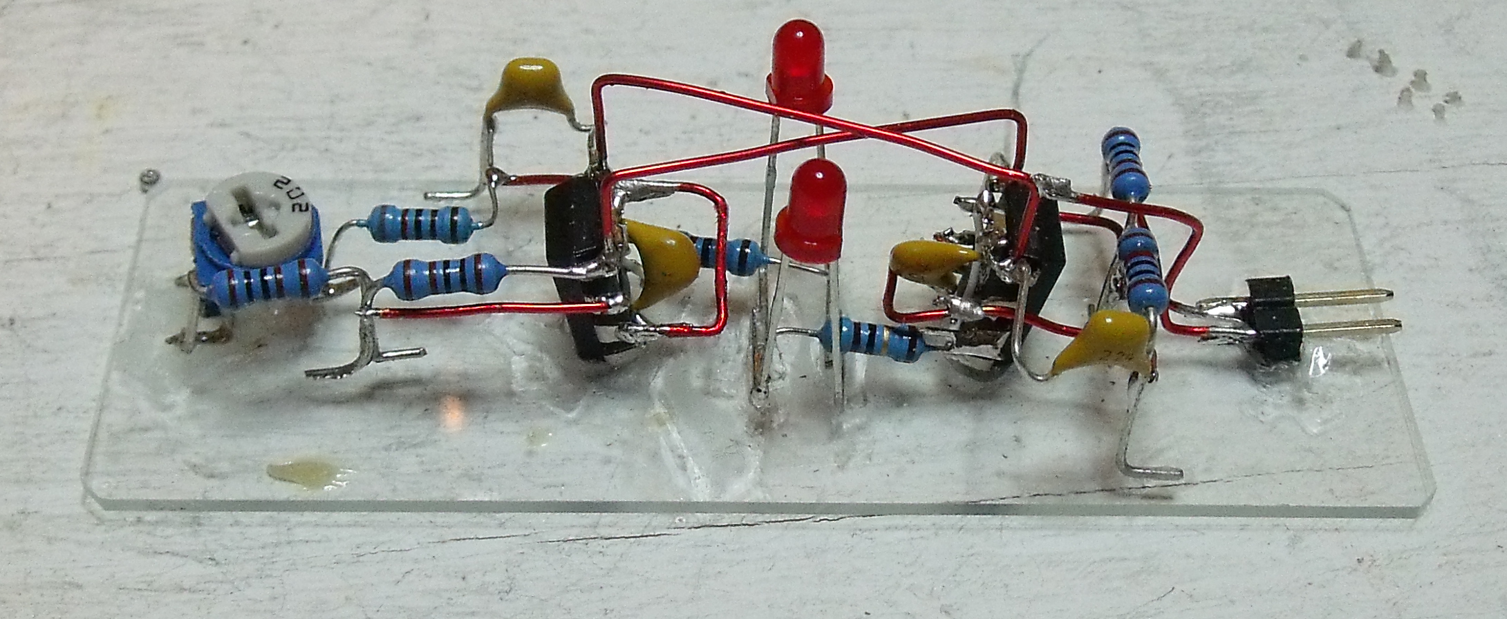
Two of them are required though. Here the schematic.
How does it works
This is based on frequencies difference. U2 frequency is adjusted by RV1 to be slightly off to that of U1. The LED is connected between the outputs of the two timers. It can light up only when U1 pin 3 is high while U2 pin 3 is low. Since the two frequencies are slightly different the phase between the two slip continually so that the time the LED is on is a fraction that is variable. The video below show the circuit in action as well the output of both 555 on oscilloscope. One can see the slipping of the blue trace compared to yellow trace.
 Jacques
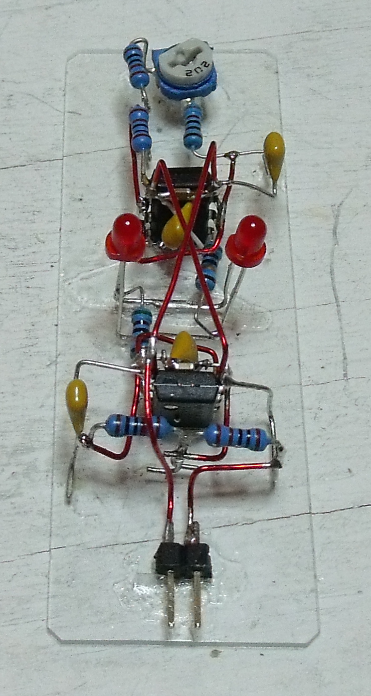
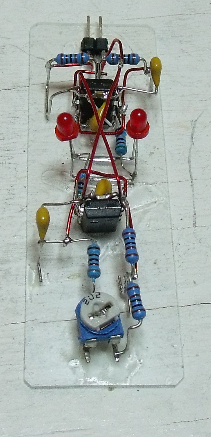
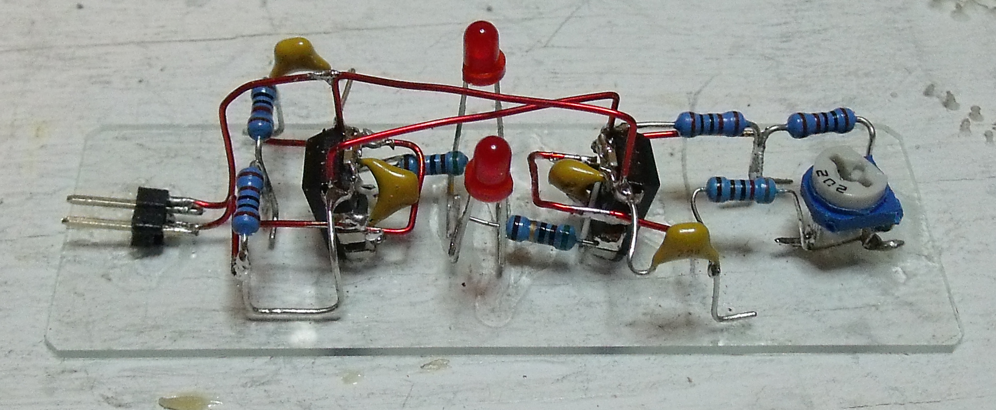

"Usually one use a MCU to fade a LED. ".
That's really funny. 20 years ago that would have been an insane statement..;-)