 Ted Yapo
It was a long day in the lab, but I got it working. There are actually four oscilloscopes in this picture: three commercial ones, and one homebrew version on those copper clad boards. Right now, it has the most primitive interface you can imagine - you turn a 20-turn potentiometer to set the time at which you want to sample the input waveform, then read the voltage at that time off a voltmeter. But, even with this insanely stupid interface, it still has a higher bandwidth than the DS1054Z at the back of the table. I measured the bandwidth of the new sampling scope at 156 MHz. Not bad for a first "toy" version.

There are a lot of things to document, and it will take a little while to get it all down, but in a nutshell, I made an adjustable time delay for the x-axis that allows you to move the sample trigger pulse by about 10 ns, with resolution of maybe 30-40 ps (limited by jitter). Using this, I was able to capture a trace of the fall of a 844 ps pulse edge. The 90-10% fall time is 2.41 ns, but correcting for the fact that the input has a fall-time of 844 ps yields a 2.25 ns fall time for the sampler itself. Using the old 0.35/t rule, this front-end has a bandwidth of 156 MHz.
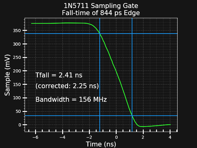
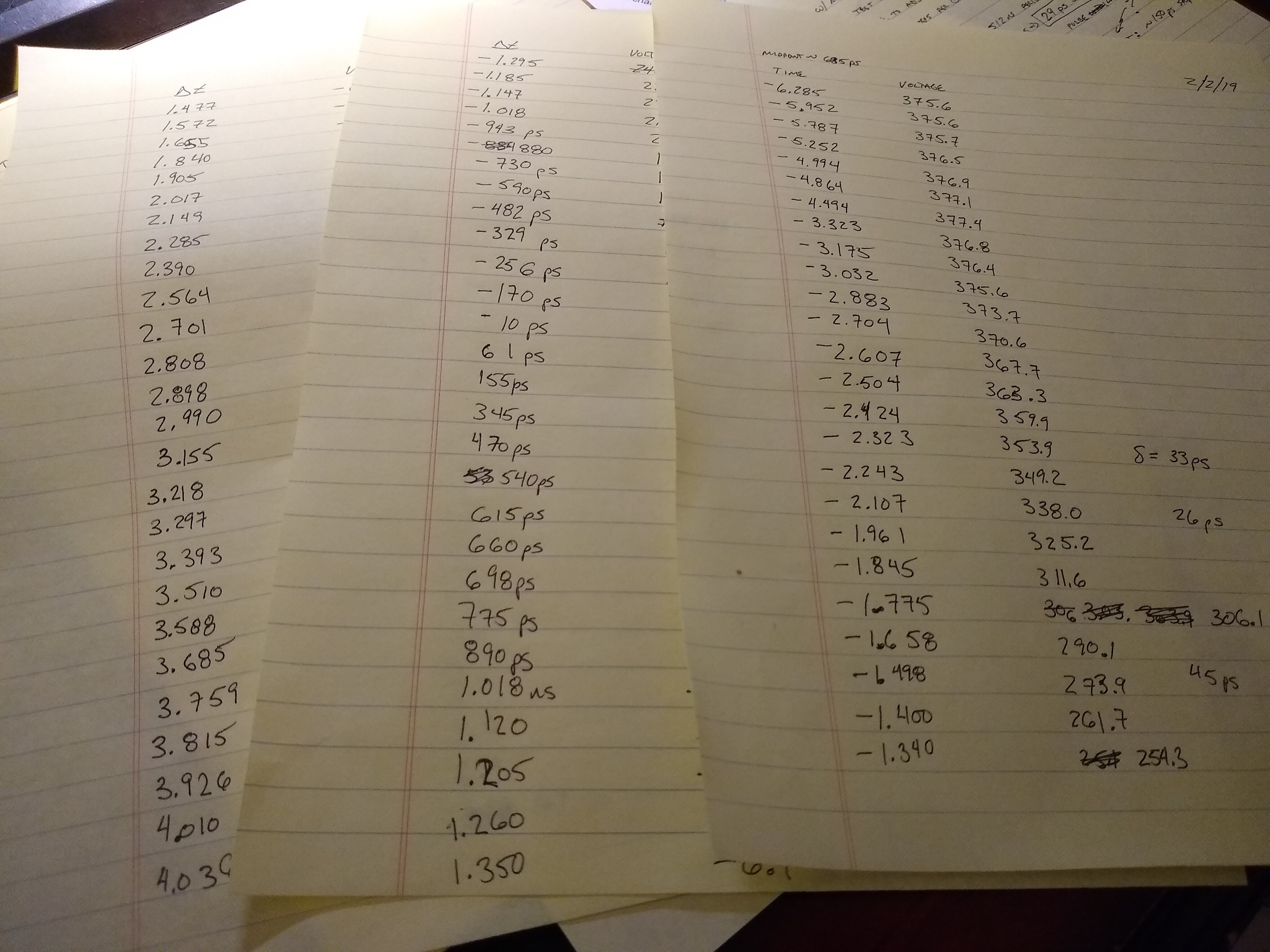
This plot was created from 79 data points taken by hand. For each one, the delay time was adjusted slightly with the potentiometer, then the voltage was read from a voltmeter. I wrote all the points down on paper. Because of the slow data collection, there's an insane amount of averaging going on. The pulse had a frequency of 1 MHz, and assuming it may have taken me 10-15 seconds to collect each point, there could be 10 million samples averaged to get this result. That's why you don't see any noise.
I think I'll have to automate this before the next test.
Next Up
I have to document the variable delay and pulse generator used to capture this data. But right now I'm tired and am going to sleep.
Discussions
Become a Hackaday.io Member
Create an account to leave a comment. Already have an account? Log In.
This log made me double check that I have liked this project!
PS Struggling with the inductor measurements but it's limited time available rather than anything else.
Are you sure? yes | no
I think you just need lighter coupling to the LC.
Are you sure? yes | no
Yes. I have a bag of shiny new 10M resistors to try and achieve this in one way. Just not got around to opening them!
Are you sure? yes | no