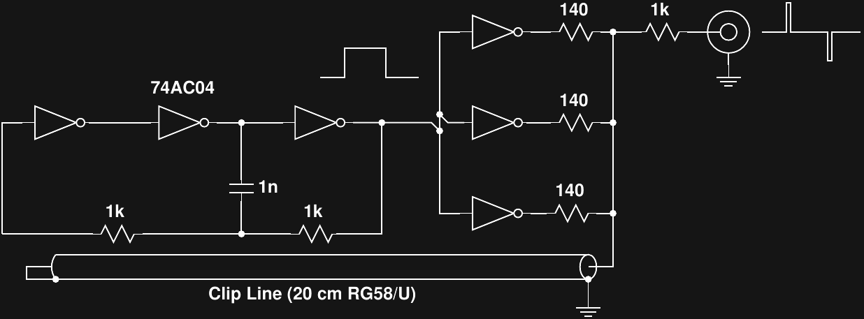
If you dig through enough schematics for old Tektronix sampling heads, you eventually come across "clip lines." The idea is to use a stub section of transmission line to shape fast pulses. To play around with the idea, I threw together a test using another 74AC04.

The circuit uses three of the inverters in the package as an RC oscillator with the remaining three paralleled through resistors to create an approximately 50 ohm driver. Three gates can't really supply enough current for use like this - you need four - but it was good enough for a quick test.
The clip line itself is a 20 cm section of RG58/U cable shorted at one end. When the output drivers go high, the line initially looks like a 50 ohm resistor (its characteristic impedance), and cuts the output amplitude by half, forming a divider with the 50 ohm output impedance. The edge of the pulse travels the length of the line, is reflected with inverted polarity by the shorted end, and returns to combine with the output. Since the reflected signal was inverted, it cancels with the driver voltage, leaving a zero output. So, the output pulse is only high for one round trip through the cable, creating a predictable, repeatable, and stable output pulse width.
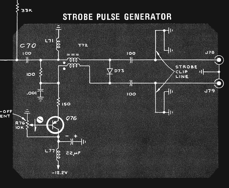
Here's how Tektronix used them in one of their samplers: the clip lines control width of the pulse created by the step recovery diode, D73. The whole thing looks awesomely simple.
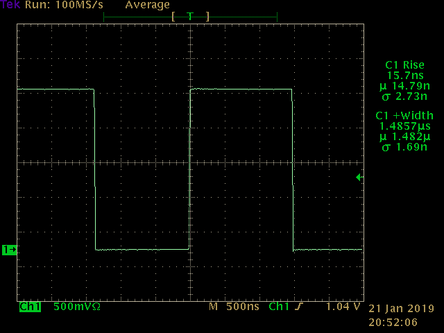
No Clip Line
The output of the pulse generator without the clip line attached is a 5V square wave with 1.48 us (yes, microsecond) positive pulse width. The rise time measurement is inaccurate at this timebase setting. The voltage scale is also wrong, since I forgot to adjust for the 20x attenuator.
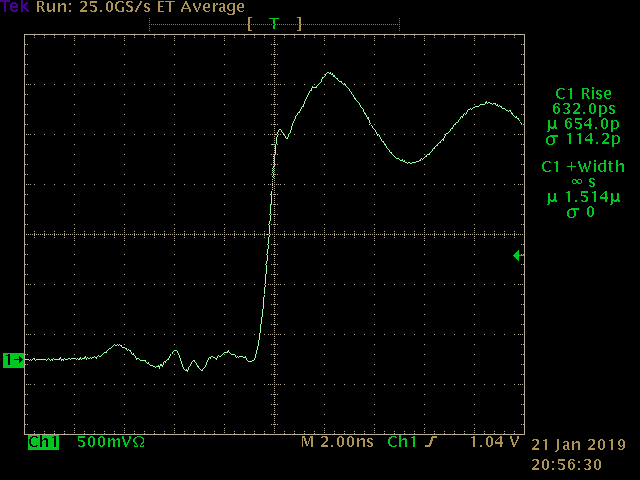
Zooming in, we can see the edge is very fast, and there's some ringing at the top of the pulse.
Now, with Clip Line
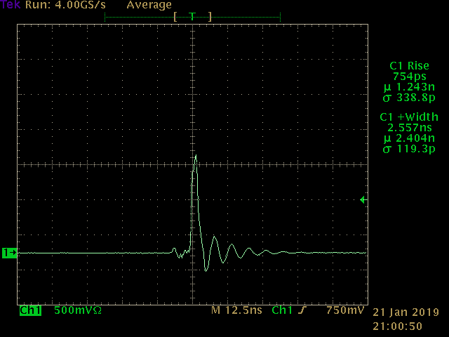
Adding the section of transmission line to the circuit transforms the output waveform into a short pulse, in this case around 2.5 ns wide. I measured the section of RG-58U cable to be approximately 20 cm long. With a velocity factor of 0.66, this should be 1.01 ns one-way, creating a pulse width of 2.02 ns. That's close enough to the measured value to be convincing - after all, the pulse isn't particularly pretty, and I don't know exactly where the scope is measuring the width.
The amplitude is also halved to 2.5 V (again, the attenuation setting on the scope was wrong).
There is also a corresponding negative pulse at the falling edge of the input signal. The scope couldn't show both on the screen at once because they are too narrow relative to the spacing.
 There's some ringing at the end of the pulse, probably because my quick test circuit doesn't present a good 50 ohm output to match the Z0 of the cable. This causes reflections of the initial edge to bounce around until they finally decay.
Conclusion
Hey, this kinda works. Maybe I should really concentrate on getting a fast, clean step and let sections of transmission line form my pulses.
 Ted Yapo
Discussions
Become a Hackaday.io Member
Create an account to leave a comment. Already have an account? Log In.