 Ted Yapo
I finally got around to populating an updated version of the SY88022AL test board. The datasheet claims typical 25 ps (20-80%) edges driving 30 mA into a 25-Ohm load. I haven't seen that yet, but it's definitely closer than last time.
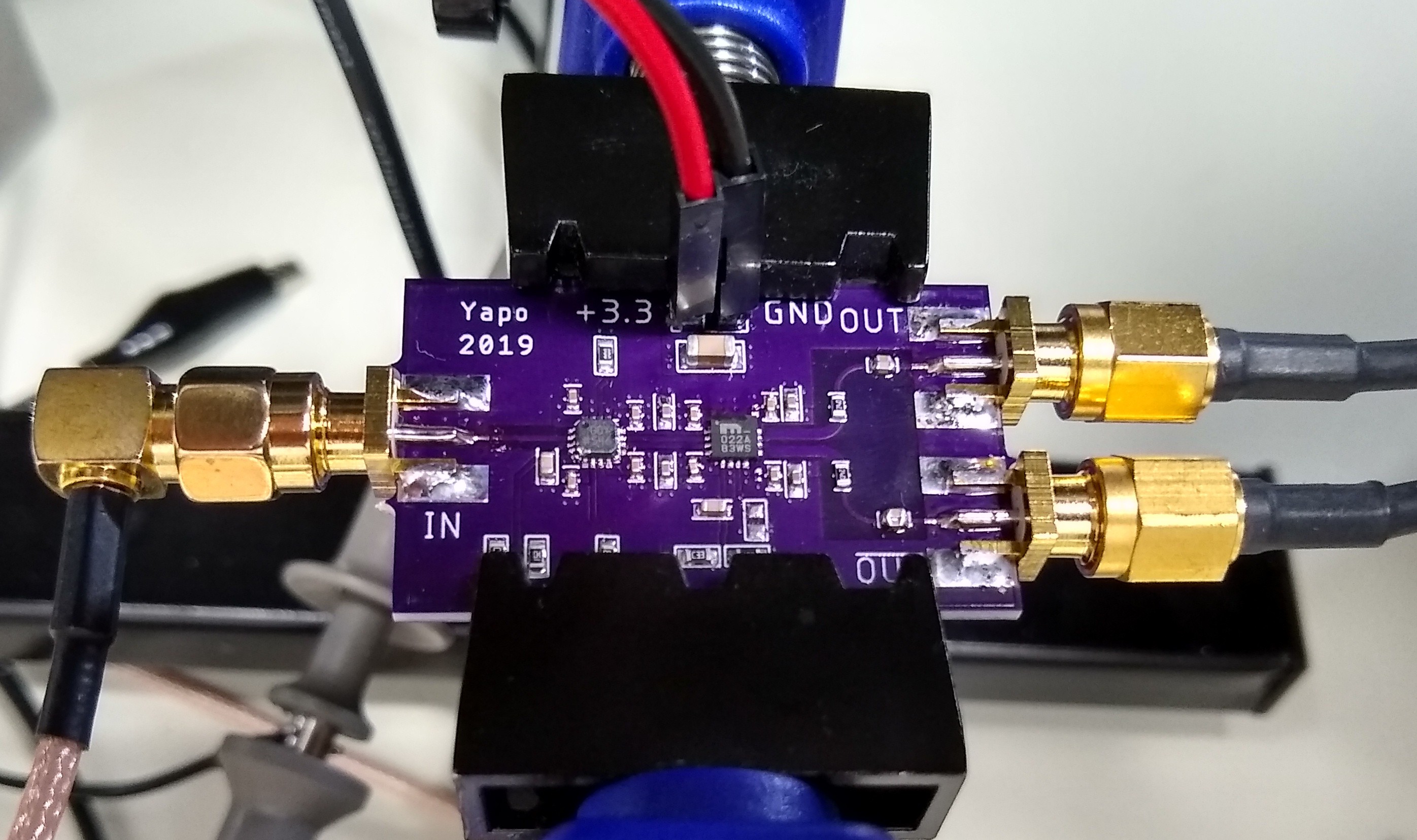
In this updated version, I drove the part with a faster CML-output comparator. The ADCMP572 has typical 20-80% edges of 35 ps, according to the datasheet. Of course, the CML outputs don't drive enough current for my needs, otherwise I could just use the comparator as the driver. This is a SiGe part, so I was a little worried about over-cooking it with the skillet reflow process, but it seems to have survived, which is nice, because they're $20 each. I may end up moving them from board to board for different tests :-)
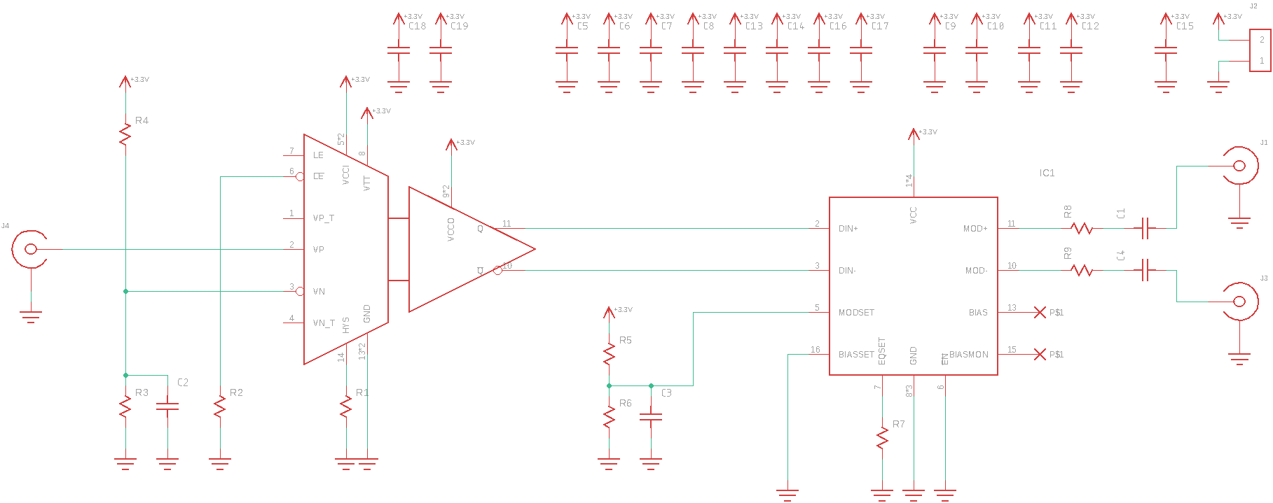
Schematic
Here's what the thing looks like -- simple, really. The comparator switches when the input crosses a threshold (set at 1V because the scope's clock output is 2V unloaded). For some reason when I made this board, I didn't use the internal 50-Ohm termination on the input pin. It doesn't seem to affect the operation since the clock output is properly back-terminated, but I'll use it next time, for sure. Then, I'll set the threshold at 500 mV. The CML outputs drive the input of the SY88022AL.
I used a ADCMP607 comparator last time, with much slower transition times of 160 ps. I was ultimately not able to get the edges out of that board better than around 70 ps, although I may re-visit it at this point.
Output
Here's around the best output I could get from this version. The transition times are around 40 ps for 10-90%. Assuming a linear rise, this is roughly equivalent to 30 ps 20-80%. The datasheet claims 25 ps typical, and I could easily see losing a few ps in the cabling and connectors.
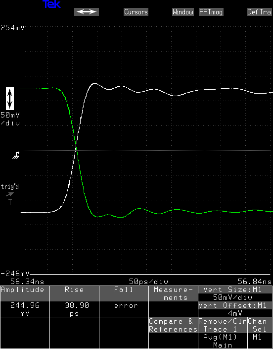
What bothers me about the output, though, is that I can only get these edge speeds for what I would consider very low output levels. I changed the output driver current to see what effect this would have
250 mV
In this case, I adjusted the output current to yield a 250 mV output amplitude. The output is loaded with 74 Ohms (50 for the scope plus a 24-Ohm series resistor to match the 25-Ohm outputs to the 50-Ohm transmission lines), so this is only delivering 3.3 mA into the load.
The datasheet numbers are specified at 30 mA, although they specify a 25-Ohm load, which equates to a 750 mV swing.
In any case, with this output amplitude, the edge rate is 38 ps.
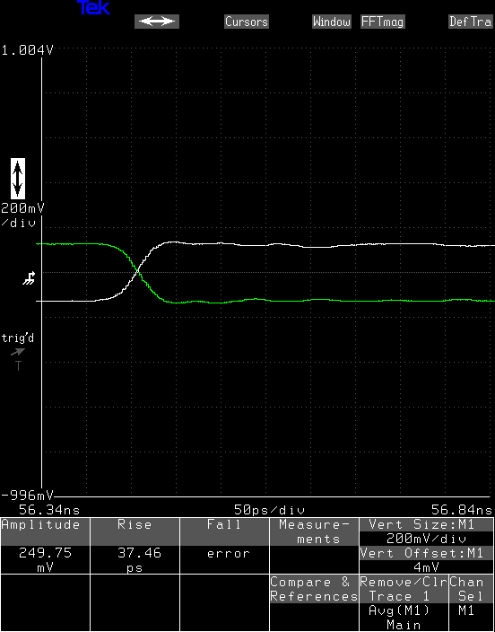
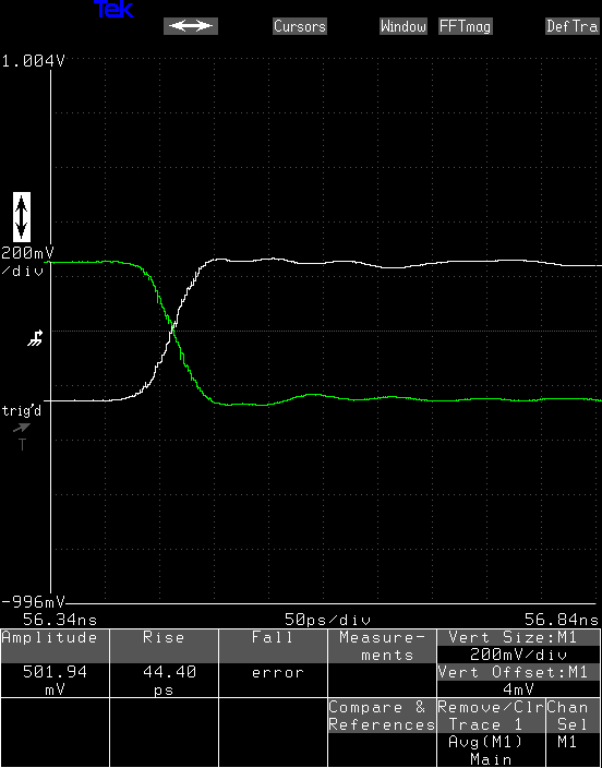
500 mV
Here, I turned the current up to yield 500 mV outputs. This is equivalent to 6.6 mA into the 75-Ohm load. The edg rates have dropped to 44 ps.
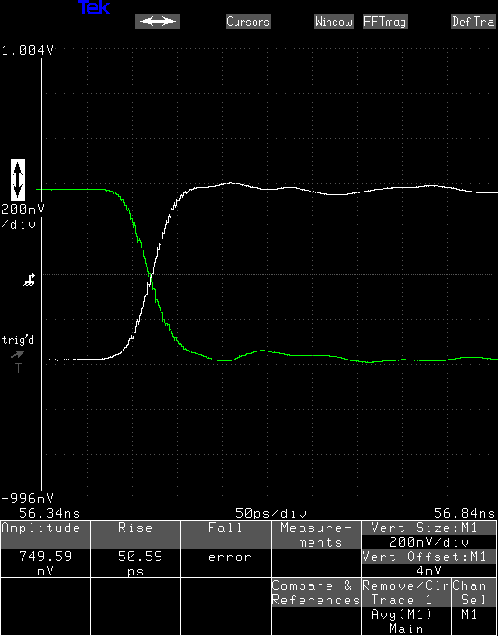
750 mV
At 750 mV output swing, equivalent to 9.9 mA into the load, the edge rates are now 51 ps.
1000 mV
Finally, at a 1 V output swing, the edge rate has increased to 68 ps. This is 13.2 mA into the load.

At this level or higher, the output starts to take on a different character - you can see the second, slow, slope in the falling edge. This may be where the output drivers have hit their compliance-range limit, although that really shouldn't happen until around 2 V outputs, according to the datasheet. Below these levels, the relationship between the output levels and transition times seems roughly linear, implying a slew-rate limiting. You can see it in the following plot, where a line had been fit to the lower three levels, with the 1 V output clearly an outlier.
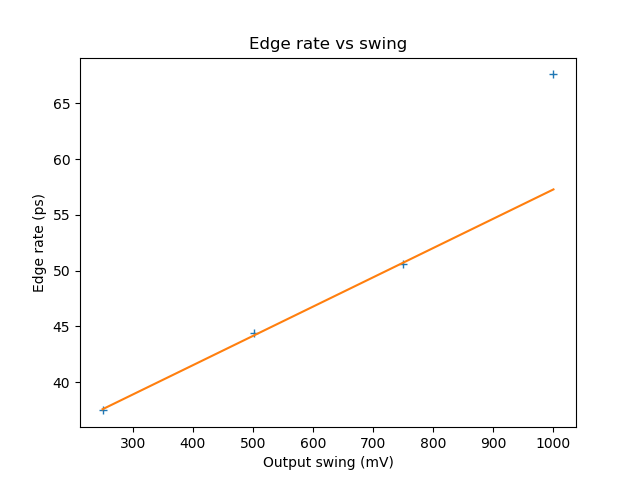
This model implies there's some fixed lower limit for the transition times, and that the edges have a fixed slew rate. That slew rate is around 10 kV/us, which is staggeringly fast.
There's still something funny going on here, but I'm not exactly sure what. Maybe I need to revisit the previous version having had this experience.
Discussions
Become a Hackaday.io Member
Create an account to leave a comment. Already have an account? Log In.