 bornach
The H-bridge is made from 4 NPN transistors, 2 PNP transistors, and a few resistors.
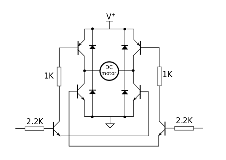
I tried to preserve some aspects of the "H" when soldering the components together. The flyback diodes were also from Dad's collection of recycled components, although I didn't show these in the build log.
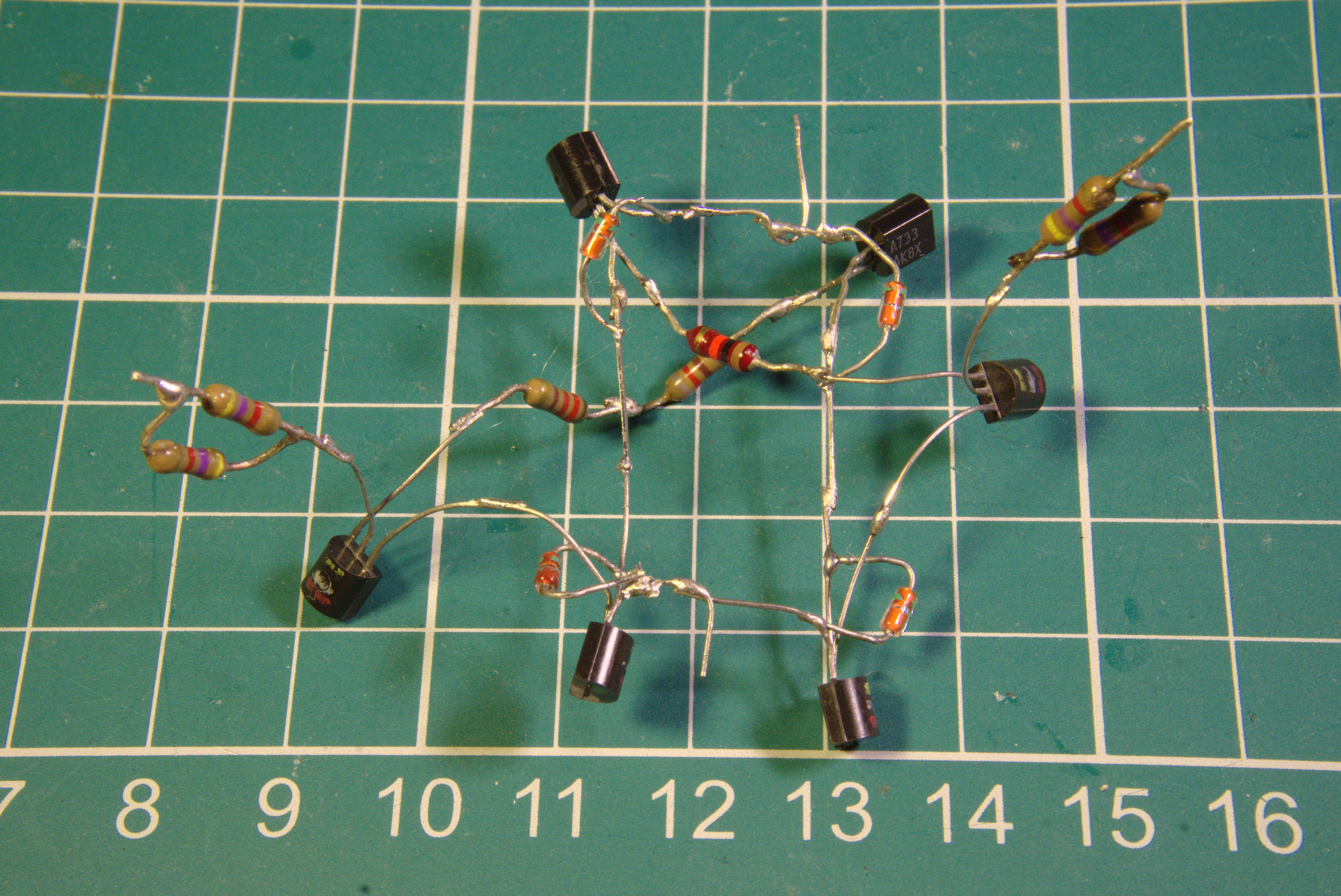
The two verticals wires join the collectors of the NPNs to the collectors of the PNPs. This is where the DC motor will be soldered in the final assembly. I couldn't find the exact resistor value as in the prototype, so I've used resistors in series and resistors in parallel where needed. I do not expect this circuit to perform optimally.
Discussions
Become a Hackaday.io Member
Create an account to leave a comment. Already have an account? Log In.