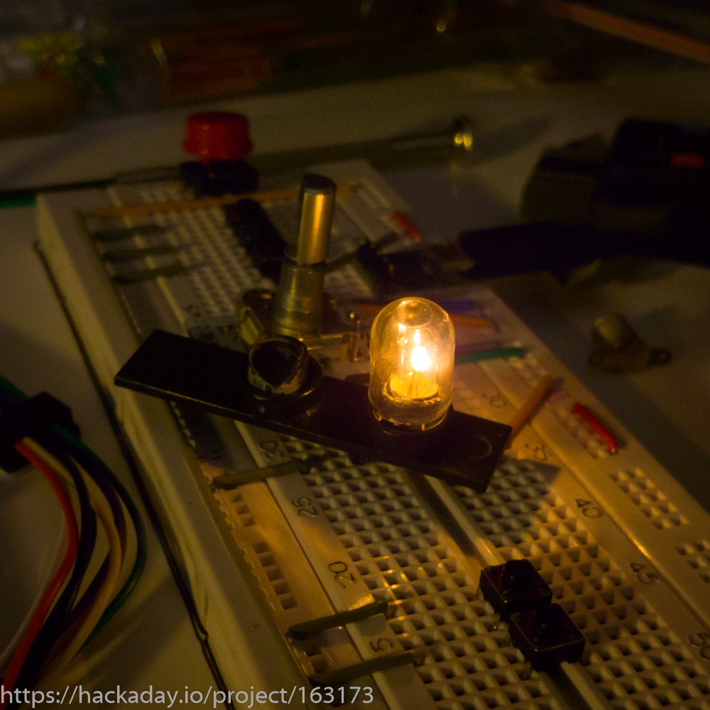
The two bulbs between the radio and geiger counter on the right hand side of the pip-boy would be easy to swap for LEDs, but I decided to go for LES bulbs instead. While the ones I got were rated for 6V, I wanted to see if I could get acceptable brightness for a 5V rail, and then switch that via a transistor from the 3V3 pi zero GPIO pins.
The existing black plastic needed to be drilled out in order to fit the new bulb holders and bulbs, and then put on a breadboard to test out. Looks like a winner to me:
Also on the breadboard I've buttons to match me intended controls embedded in the pip-boy (WIP) so I can test all the electronics independently to the build. I'll run through all that another time when I have more of it working.
Discussions
Become a Hackaday.io Member
Create an account to leave a comment. Already have an account? Log In.