Folded LED Ball v1
Some time after I finished my Polyhedrone LED ball, with a diameter of about 32cm, a friend of mine asked if I could make a small one, for on a necklace.
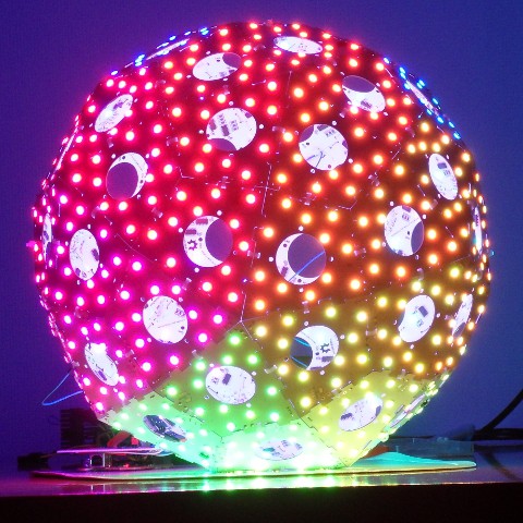
This started me thinking. Using separate facets would become very fiddly very soon at such small scales. But what if I could make the ball out of one PCB bend it into shape?
In order to accomplish this, I designed a PCB, essentially an LED strip on an unfolded half of a deltoidal-hexacontahedron. I used SK6812-3535 LEDs, which are compatible with the ubiquitous WS2812b chips, but smaller.
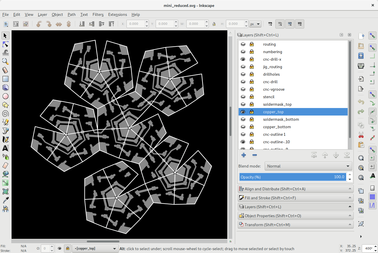
Instead of sending the PCB edges to DirtyPCBs, I ordered square PCBs instead, and milled the board myself, using the CNC mill at Frack. Additionally, I carefully milled along the fold-lines of the polyhedron from the back, drilling through (most of) the board, but leaving the copper on top intact.
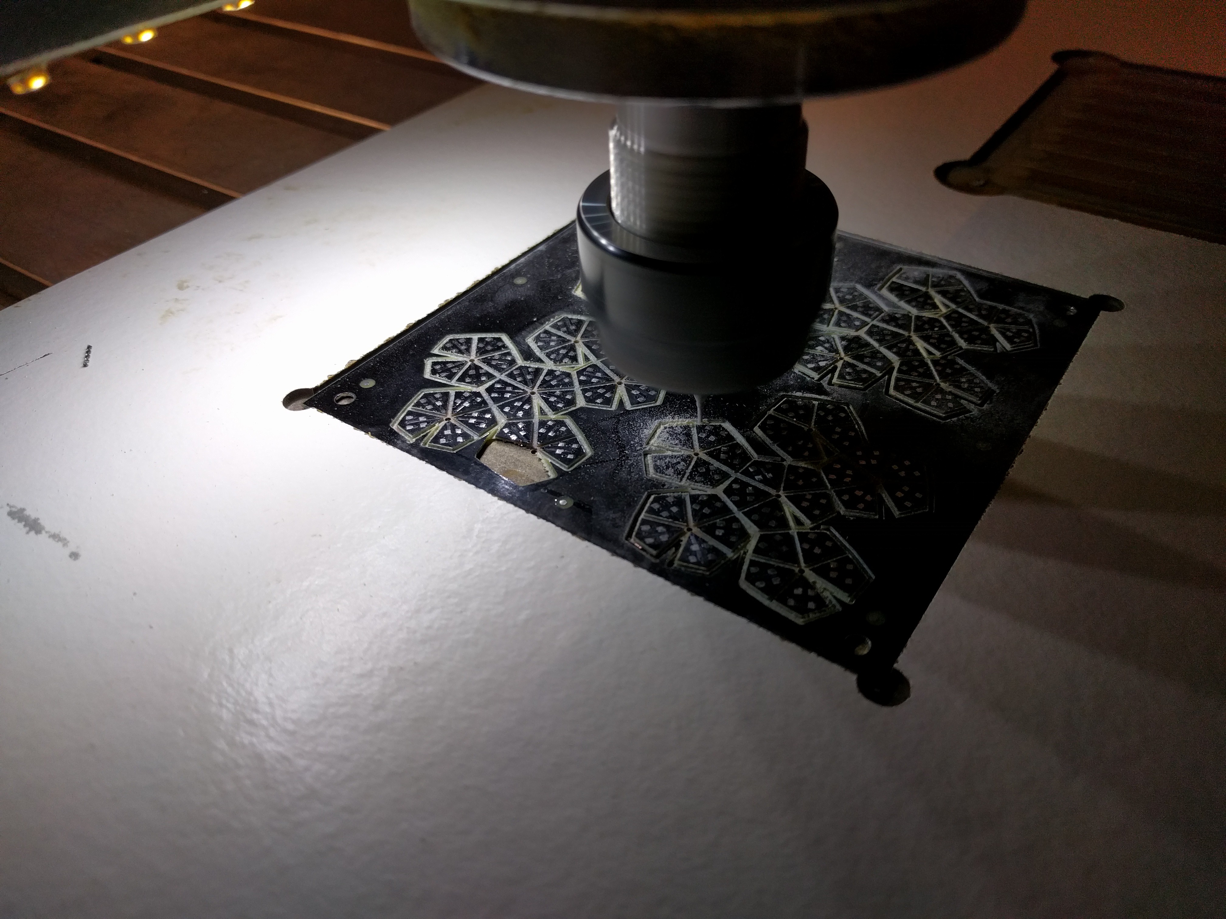
The milling tolerances are quite low, with the difference between a foldable board and a broken one being about .1mm
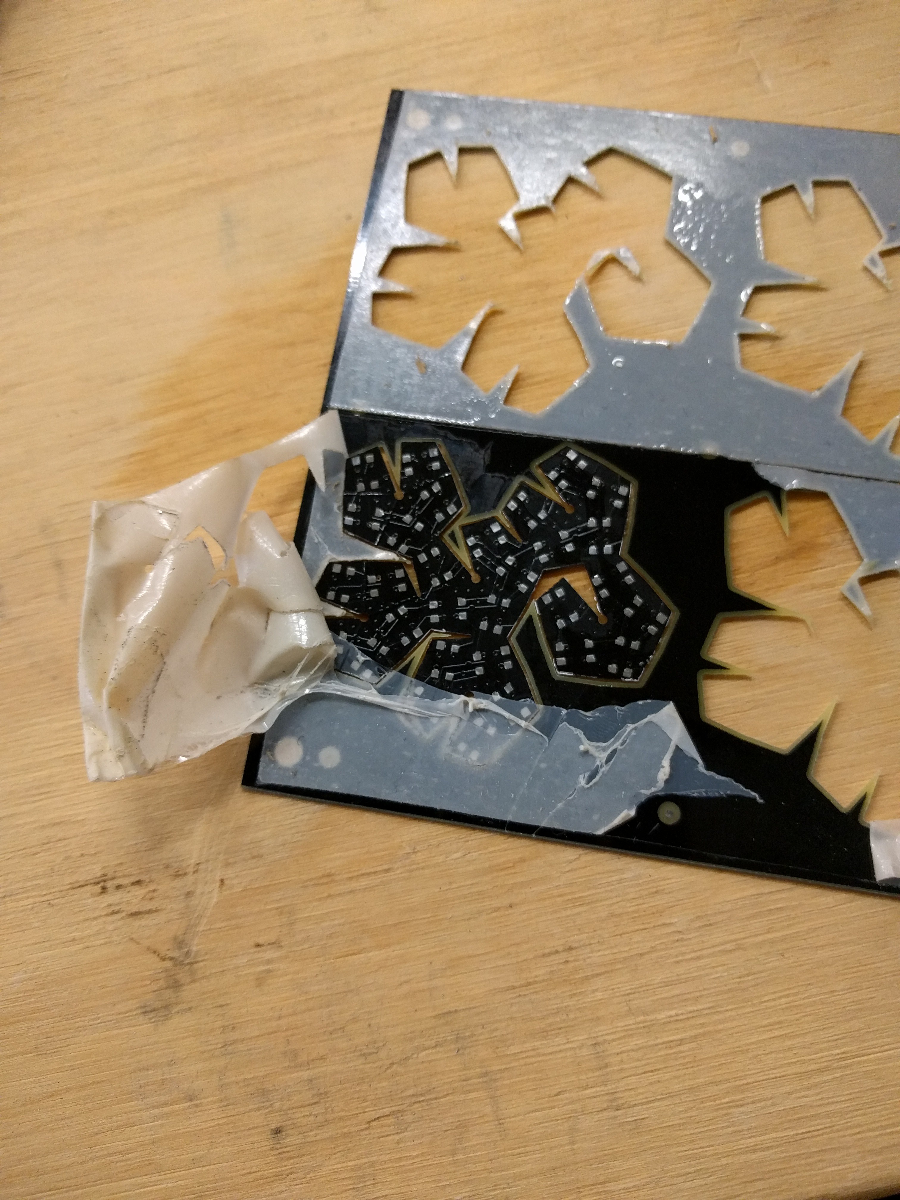
The board at this point is quite fragile, luckily, Isopropanol quickly takes care of the double-sided tape used to keep it in place during milling.
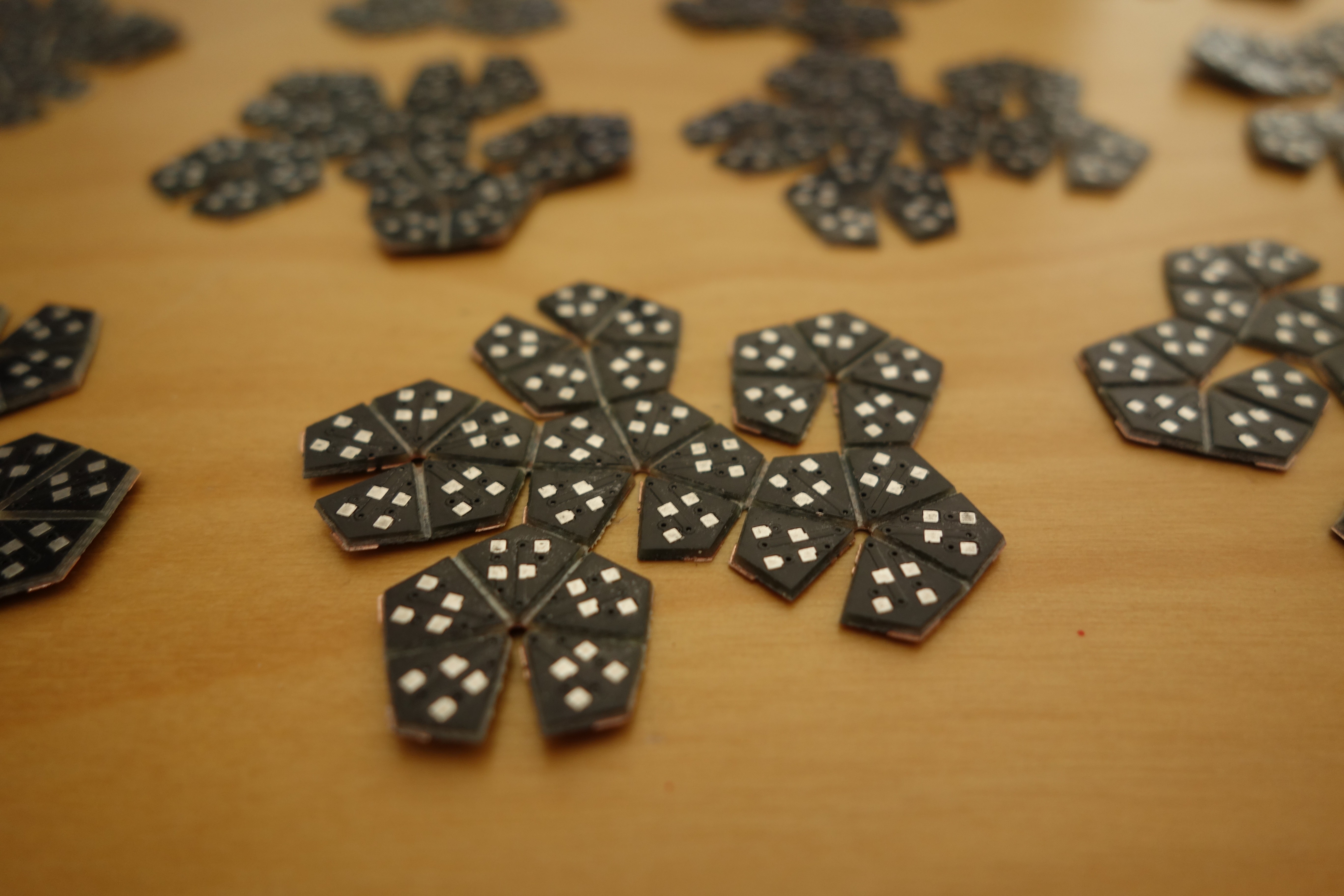
The yield at this point is about 50% :-/
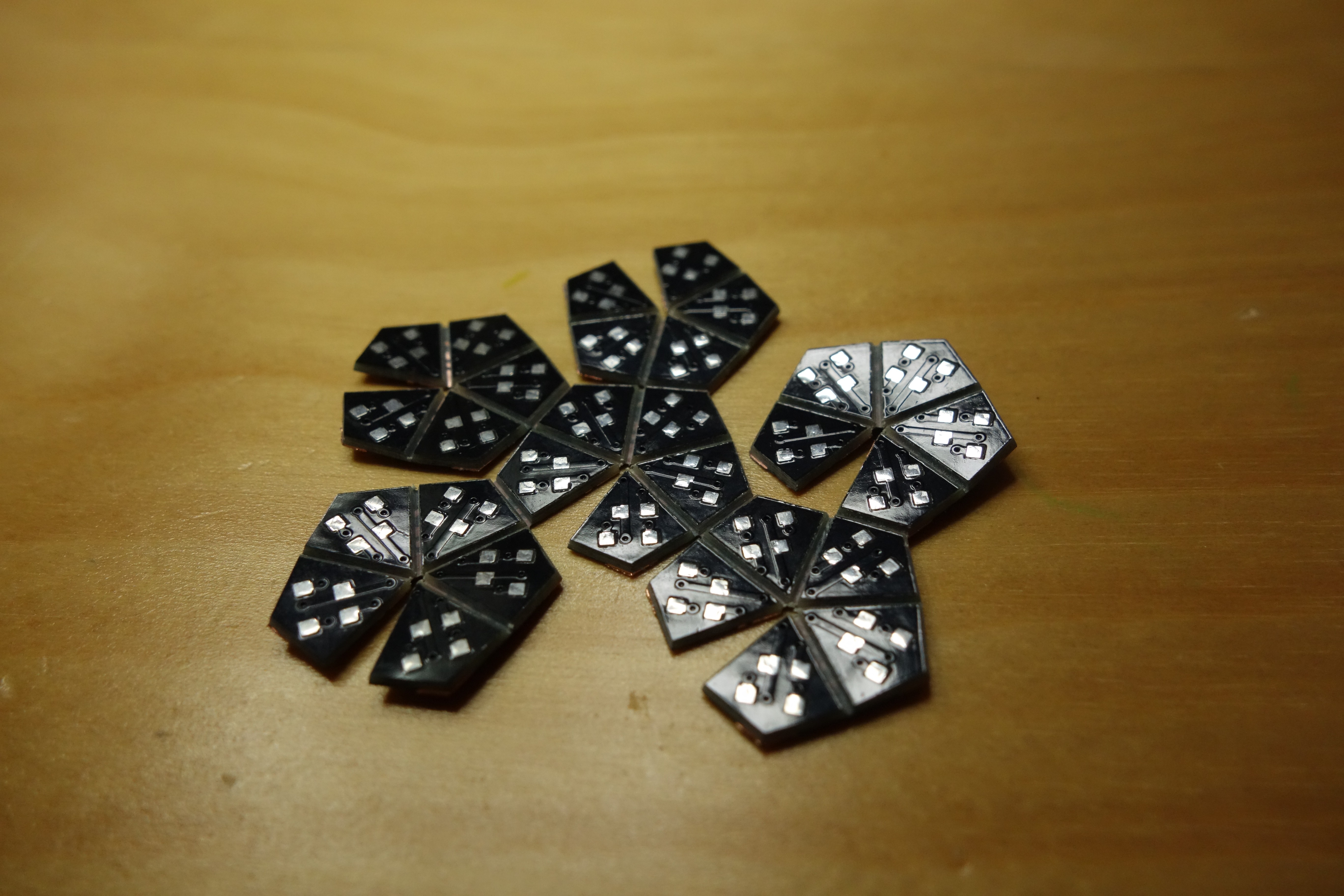
To solder the LEDs, I used a cheap electric cooking plate as hotplate.
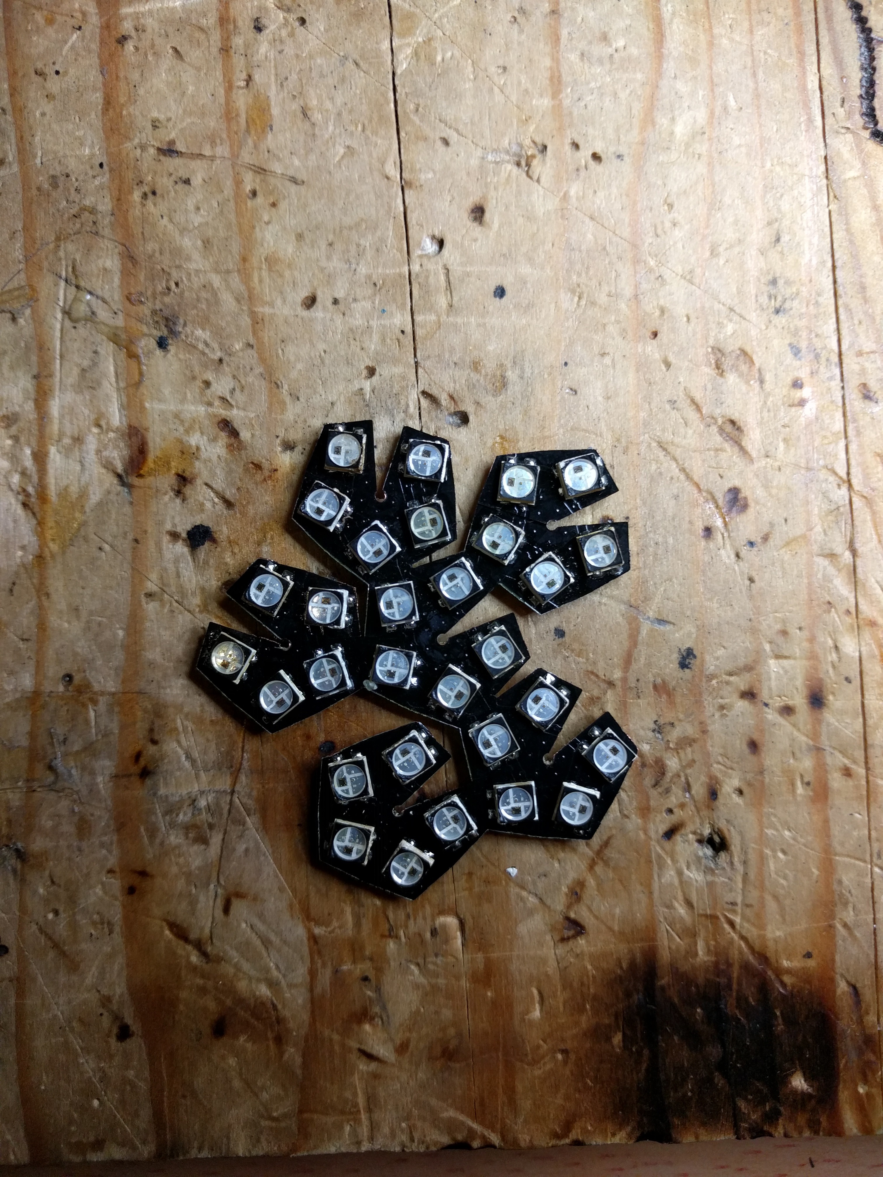 | 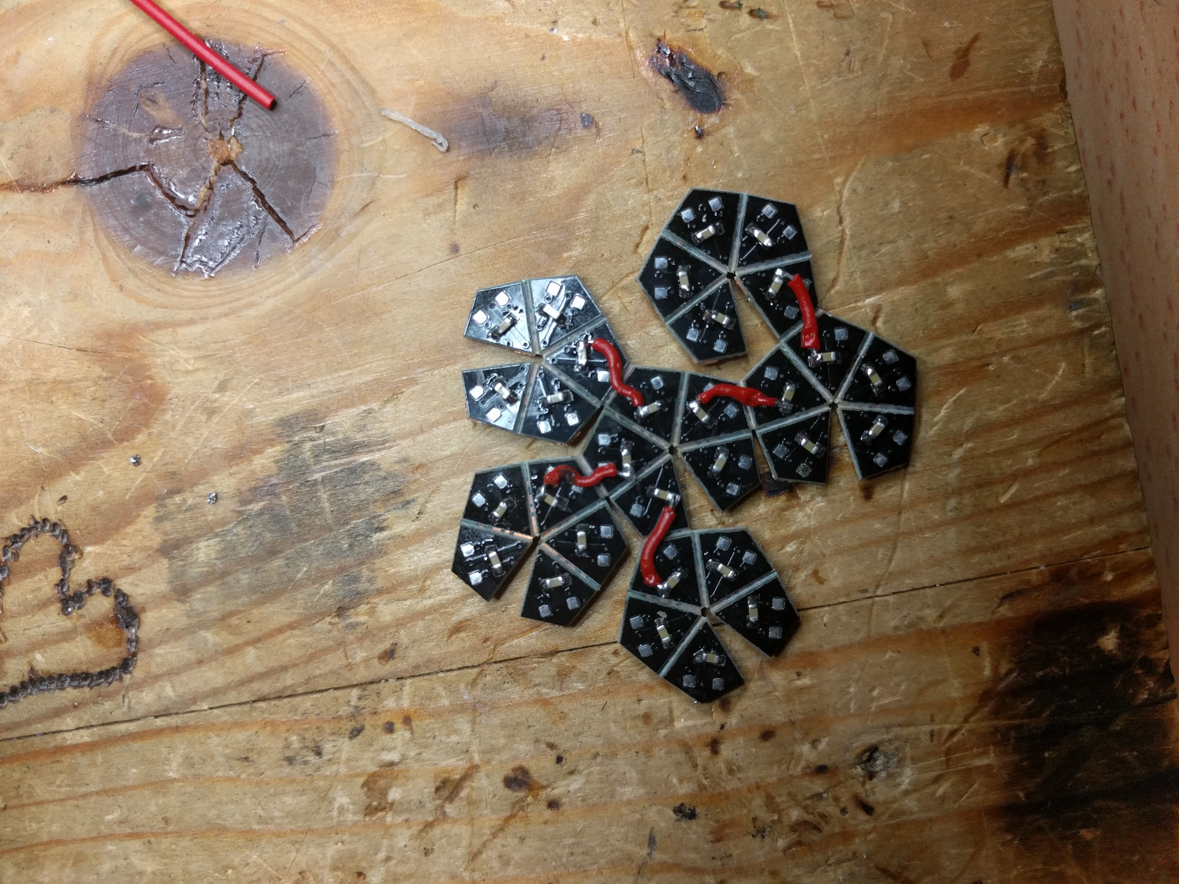 |
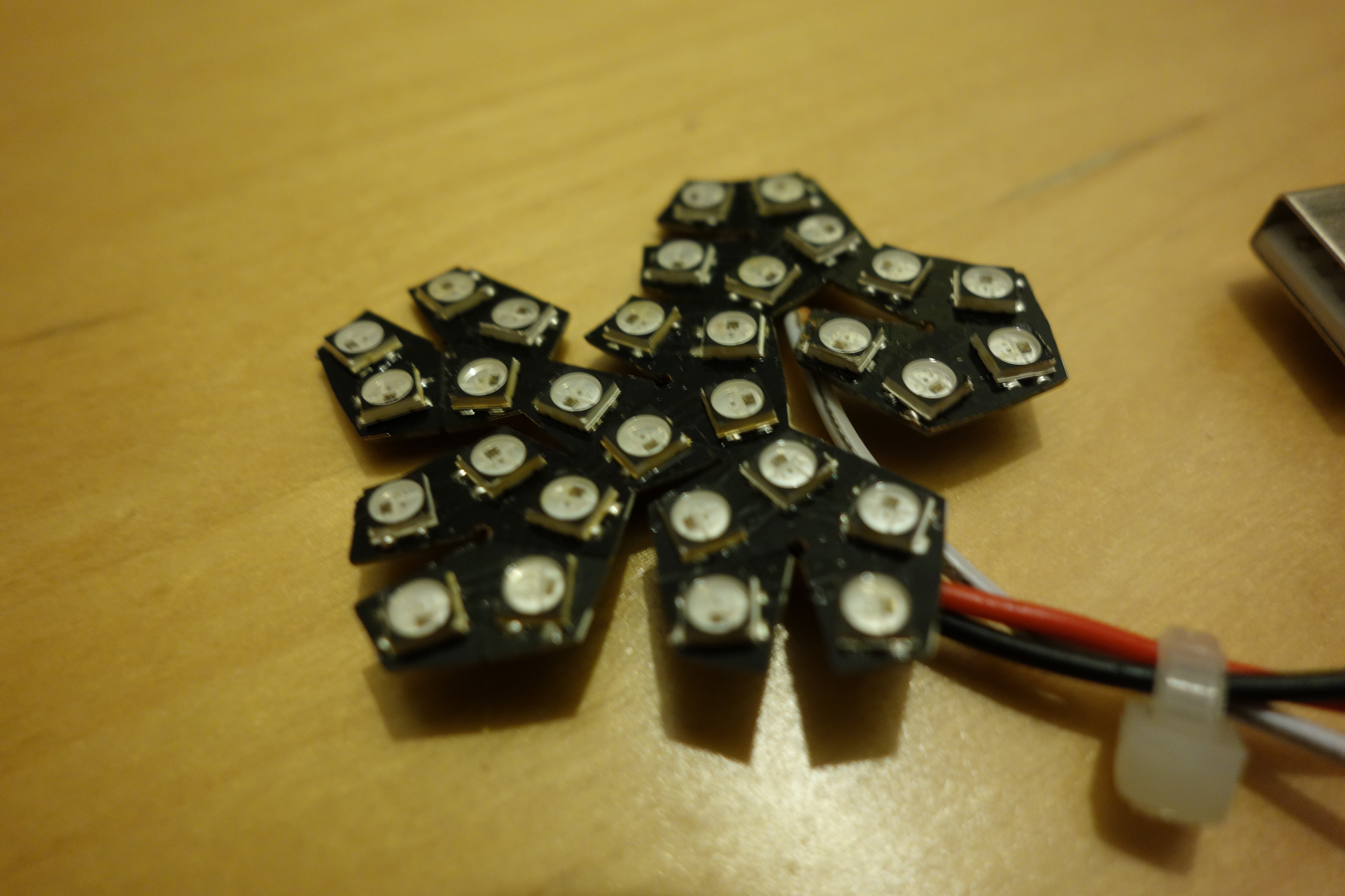 |  |
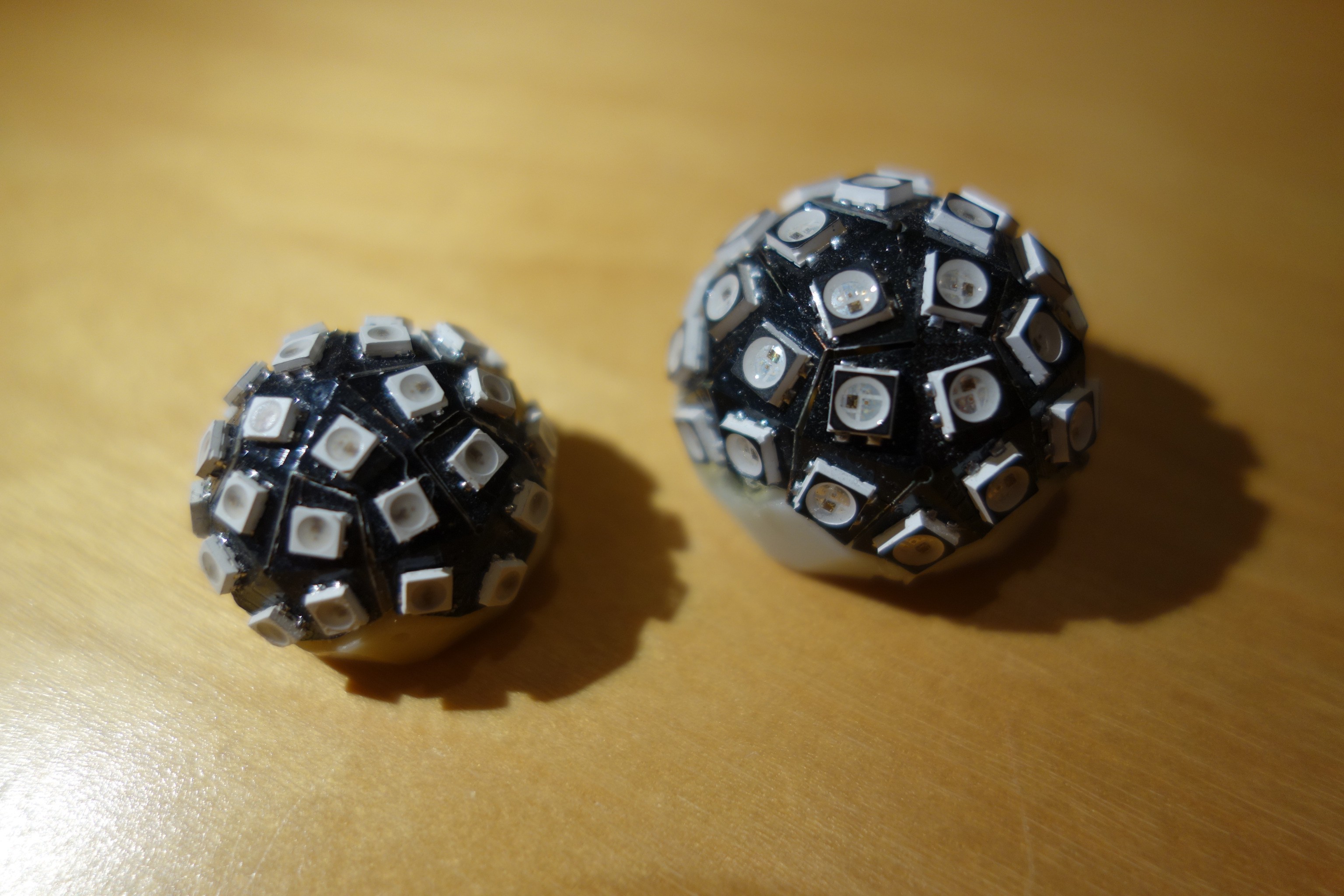
This is the moment of truth. It's time to fold, and use hot-glue on the inside to make it stay in shape:.
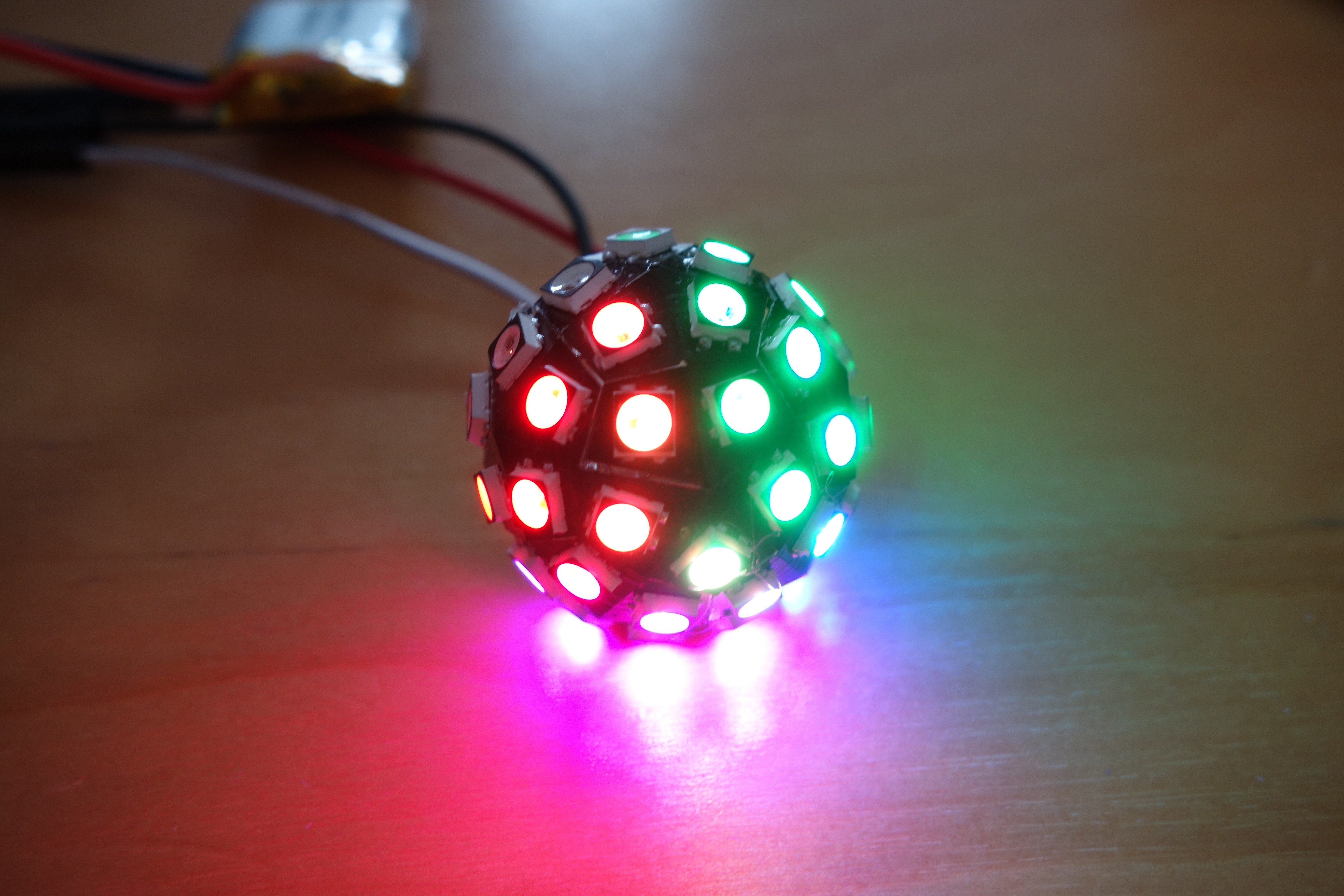
The result, (at a yield of about 25% :-/) is 30 LEDs on a half-sphere.
Driver PCB v1
To drive the ball I designed a small (13x13mm) pcb containing an attiny85 and a lipo-charging circuit and 6 pads (without holes) for an AVR isp-6 header on the backside.
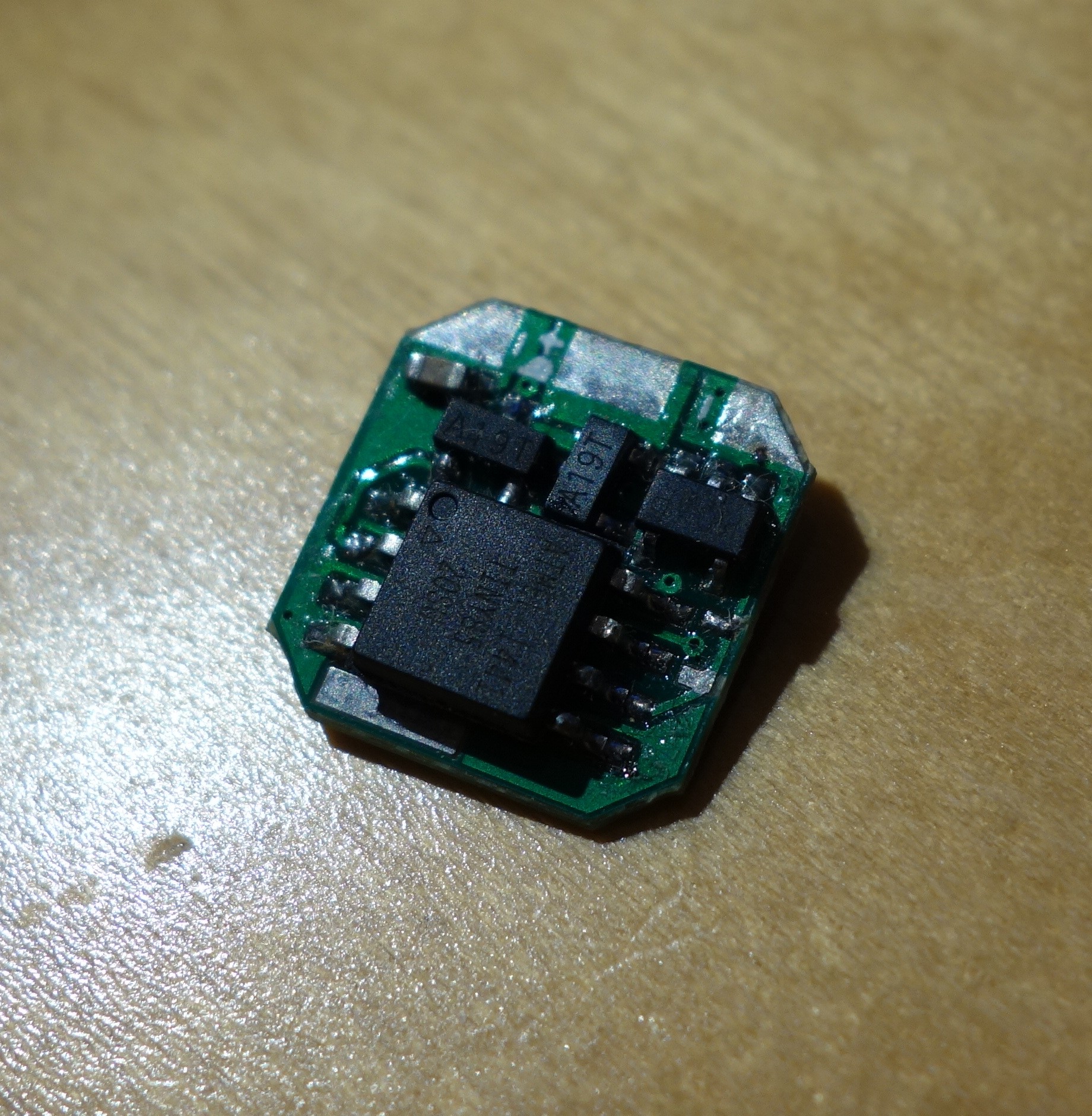
A P-Mosfet is used to allow the attiny85 to switch off the VCC line to the LEDs, mainly as a precaution to prevent a large static current draw when the lipo is nearly empty.
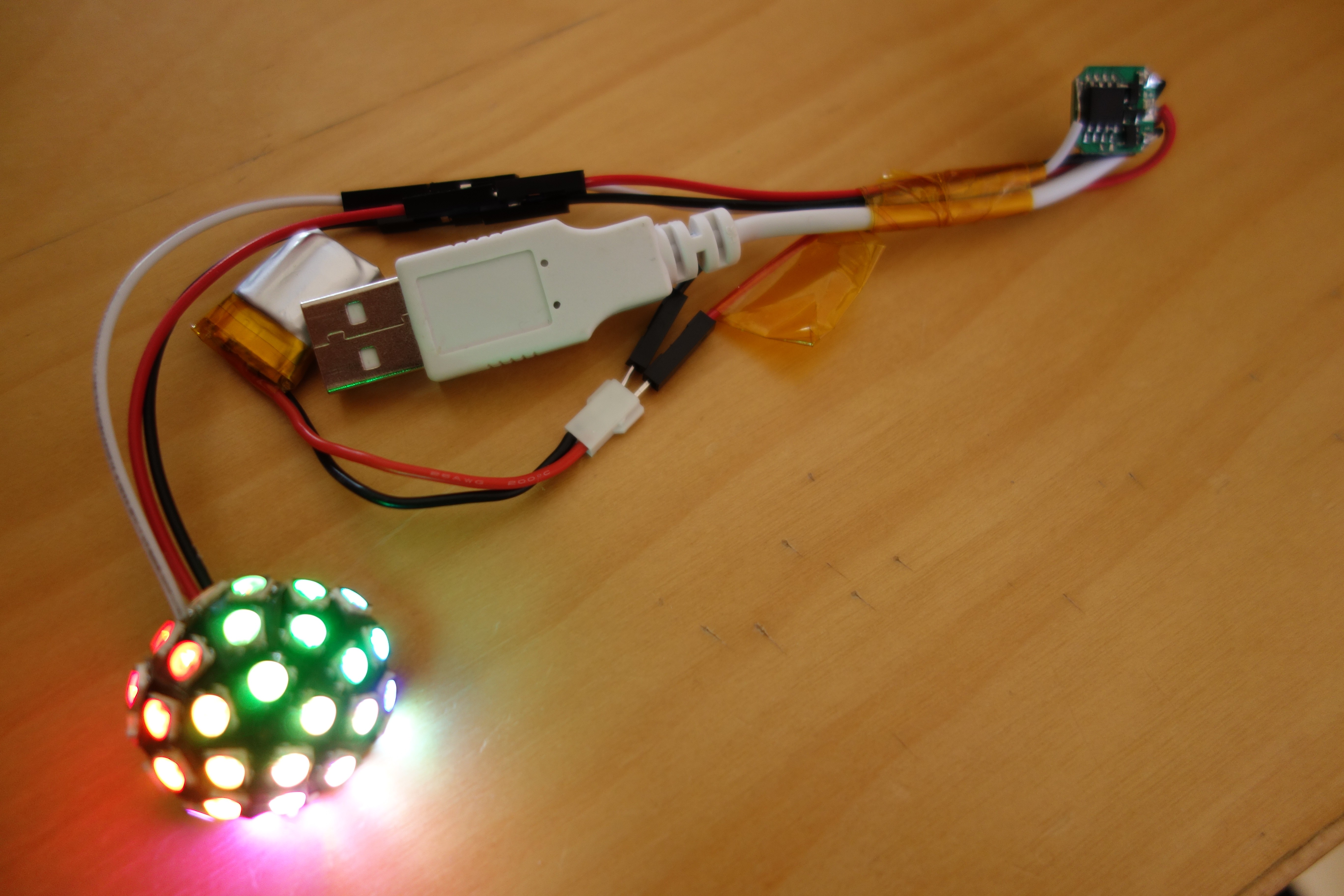
The test setup, drawing power from a lipo battery, running AVR code to perform gamma-corrected temporal dithering at 8MHz. The temporal dithering idea I borrowed from Scanlime's Fadecandy. It is pretty essential since I only drive the LEDs with brightness values [0..15], otherwise it's just too bright.
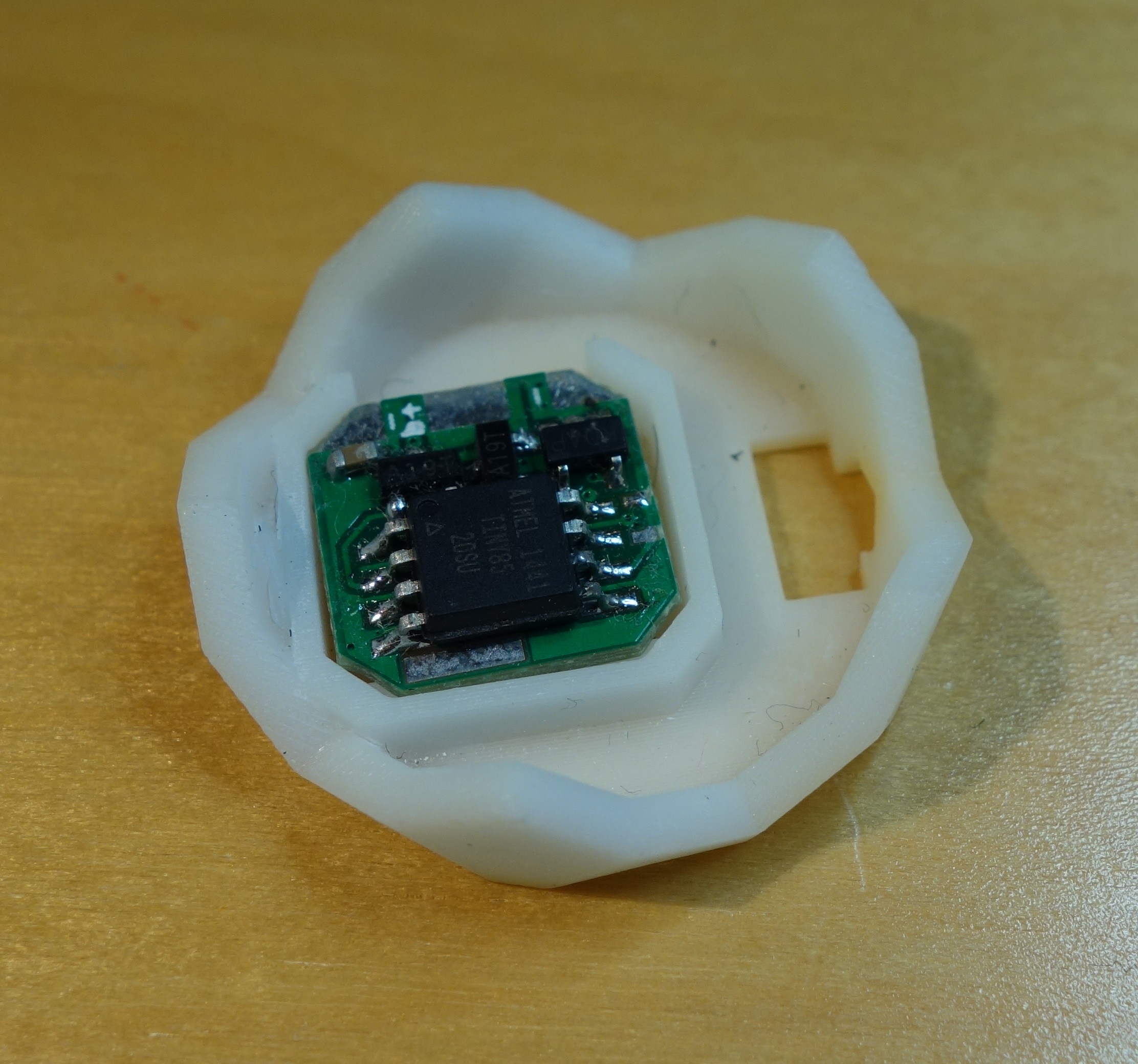
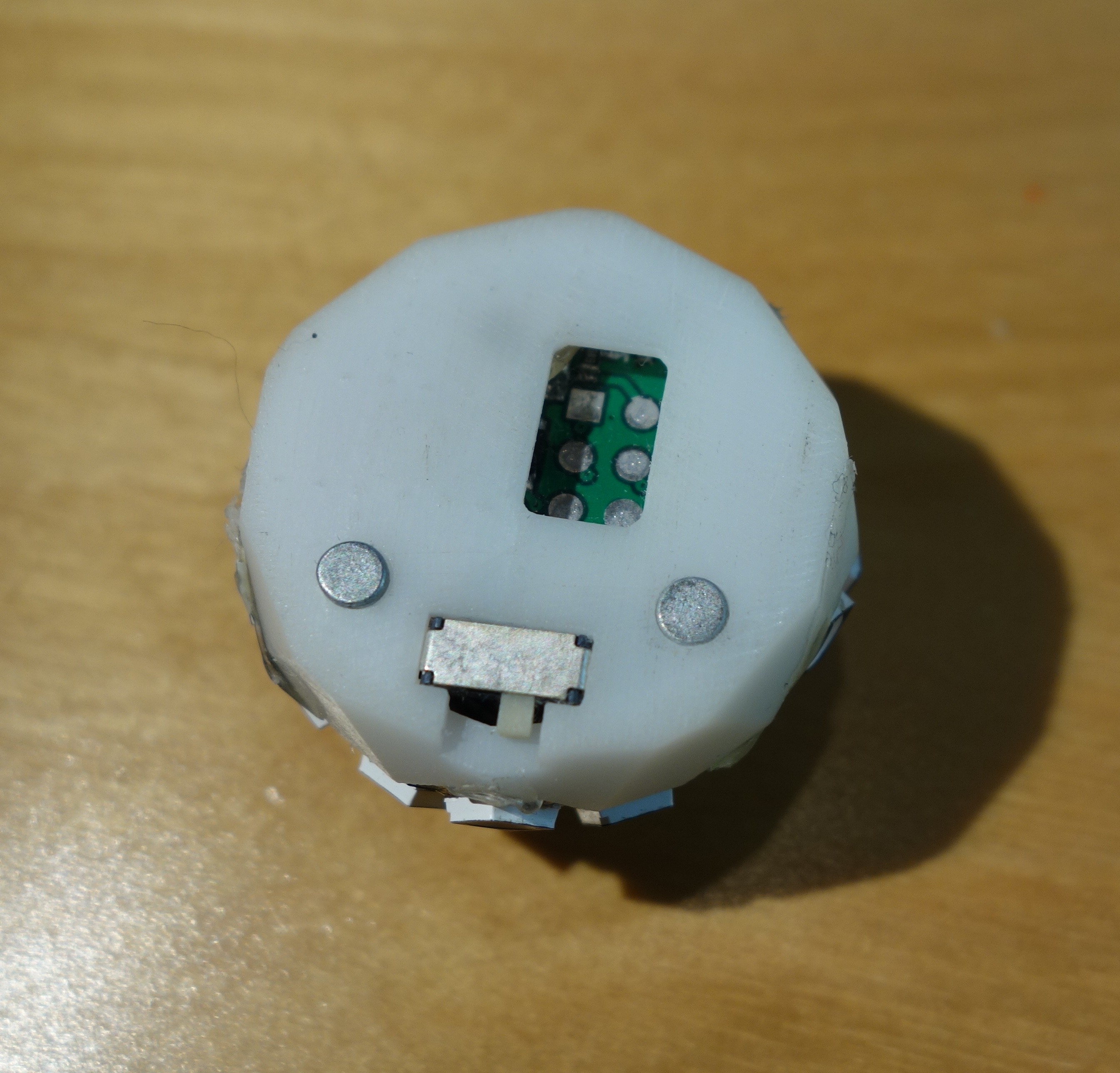
A 3D-printed base from DirtyPCBs' SLA service with room for a 7x3mm toggle switch and a tiny battery.
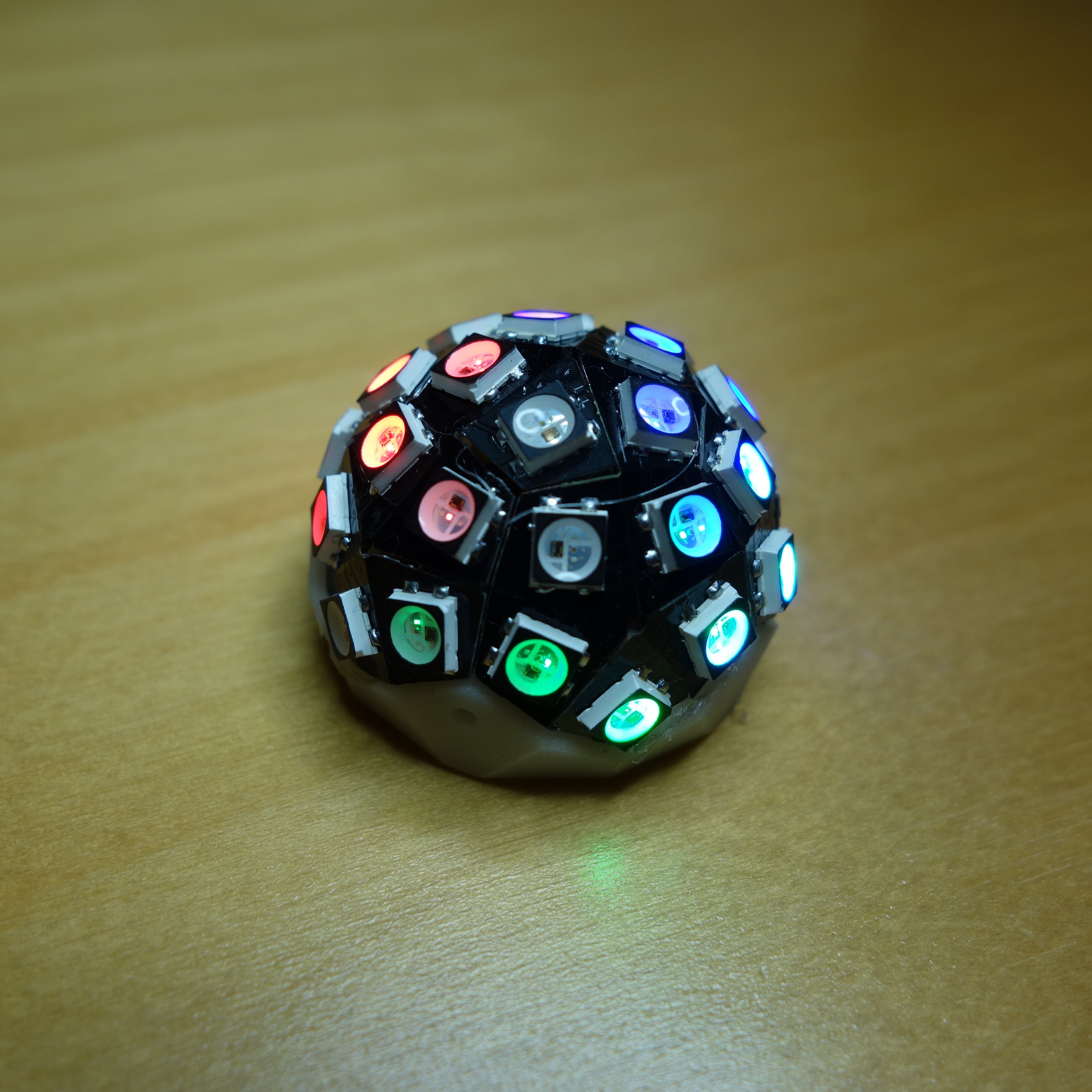
Final result: a tiny ball with a diameter of about 28mm.
Folded LED Ball v2
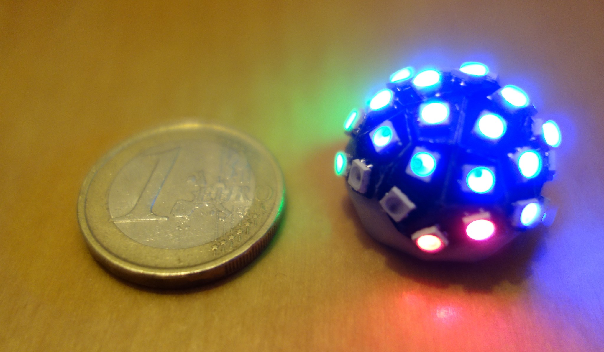
For my 2nd iteration I went for the slightly smaller SK6805-2427 LEDs, which allowed me to shrink the folded ball's diameter to 20mm, and about 22mm including LEDs.
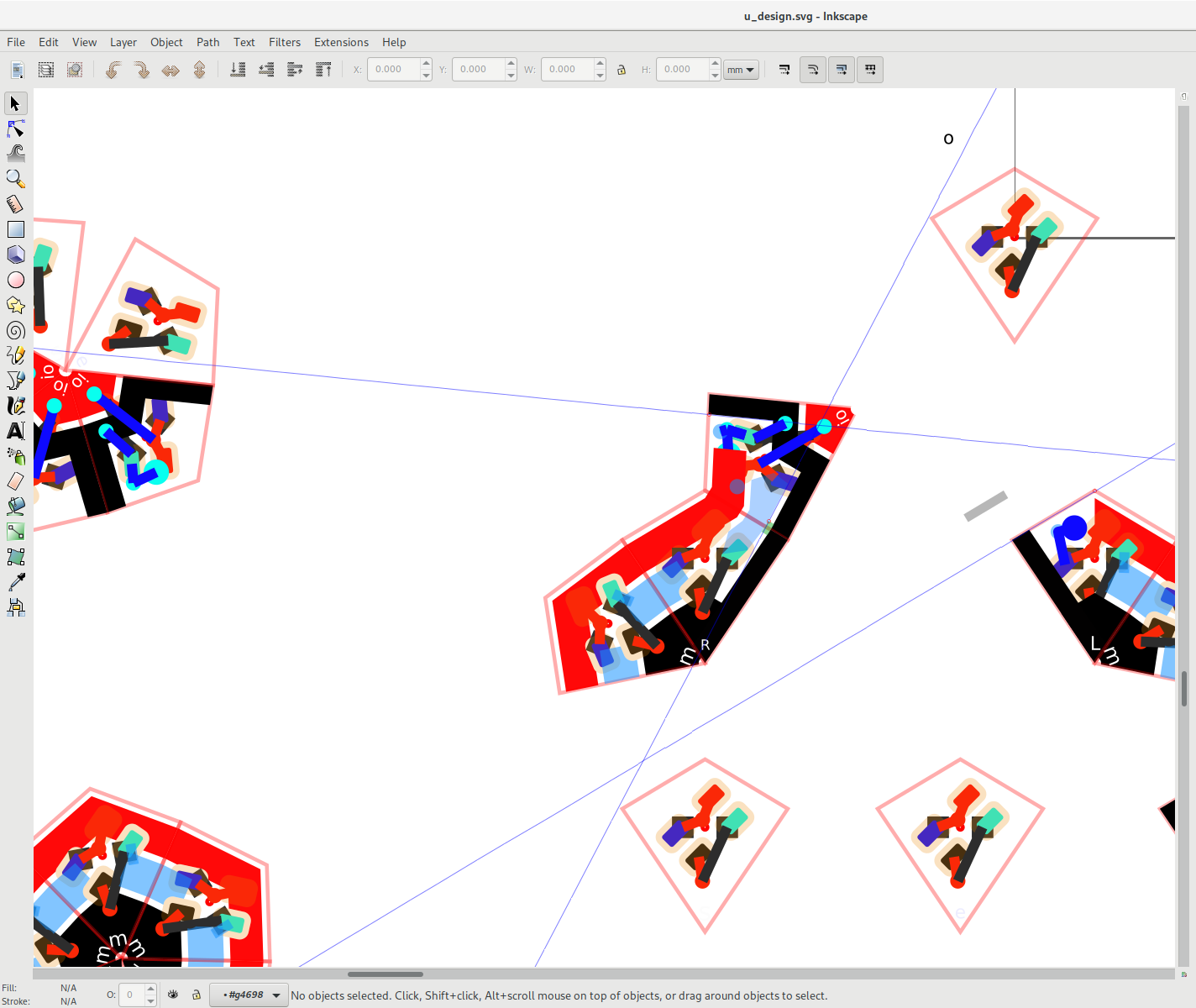
For the design I made use of inkscape's clone tool, and it's grouping functionality. By using clone to keep common elements, like the footprint and the facet outline the same across all facets, it becomes easier to manage all different variations of facets connected together. In total, there are four different configurations of facet.
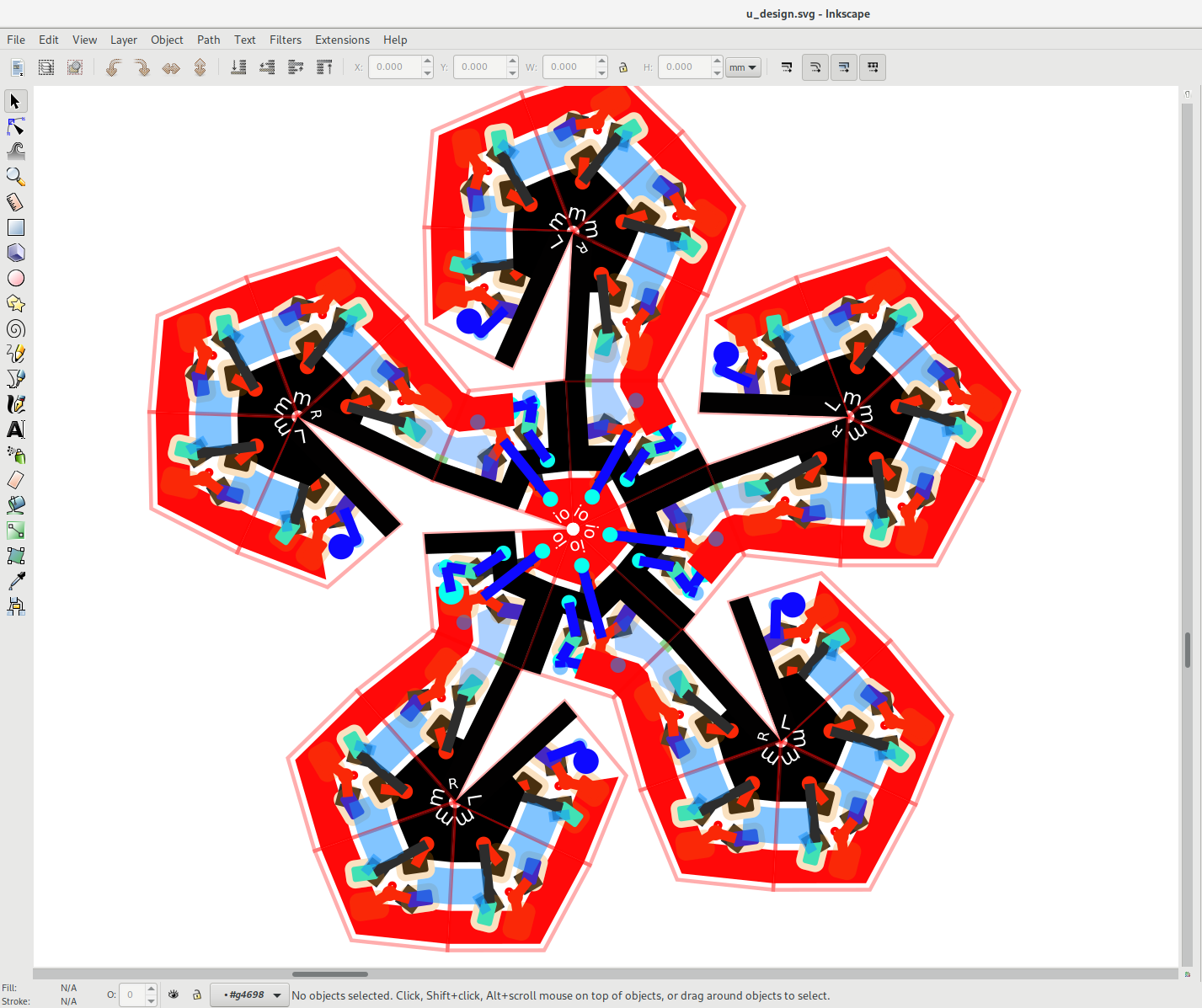
Having learned from version 1, this time I made sure the traces were as wide as possible, since too many of them broke during bending.
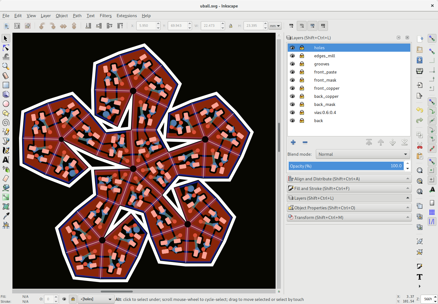
After combining all facets into simple shapes, and moving them into the right layers, I used my svgconvert script to convert them into a kicad module.
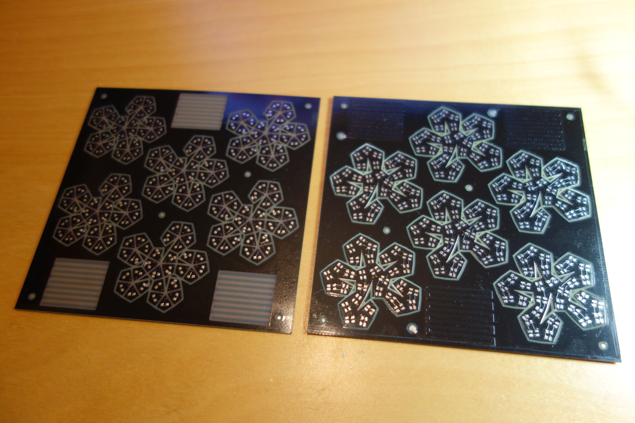
In addition to wider traces, I ordered double-thickness copper PCBs this time. Which helped quite a lot with the yield.
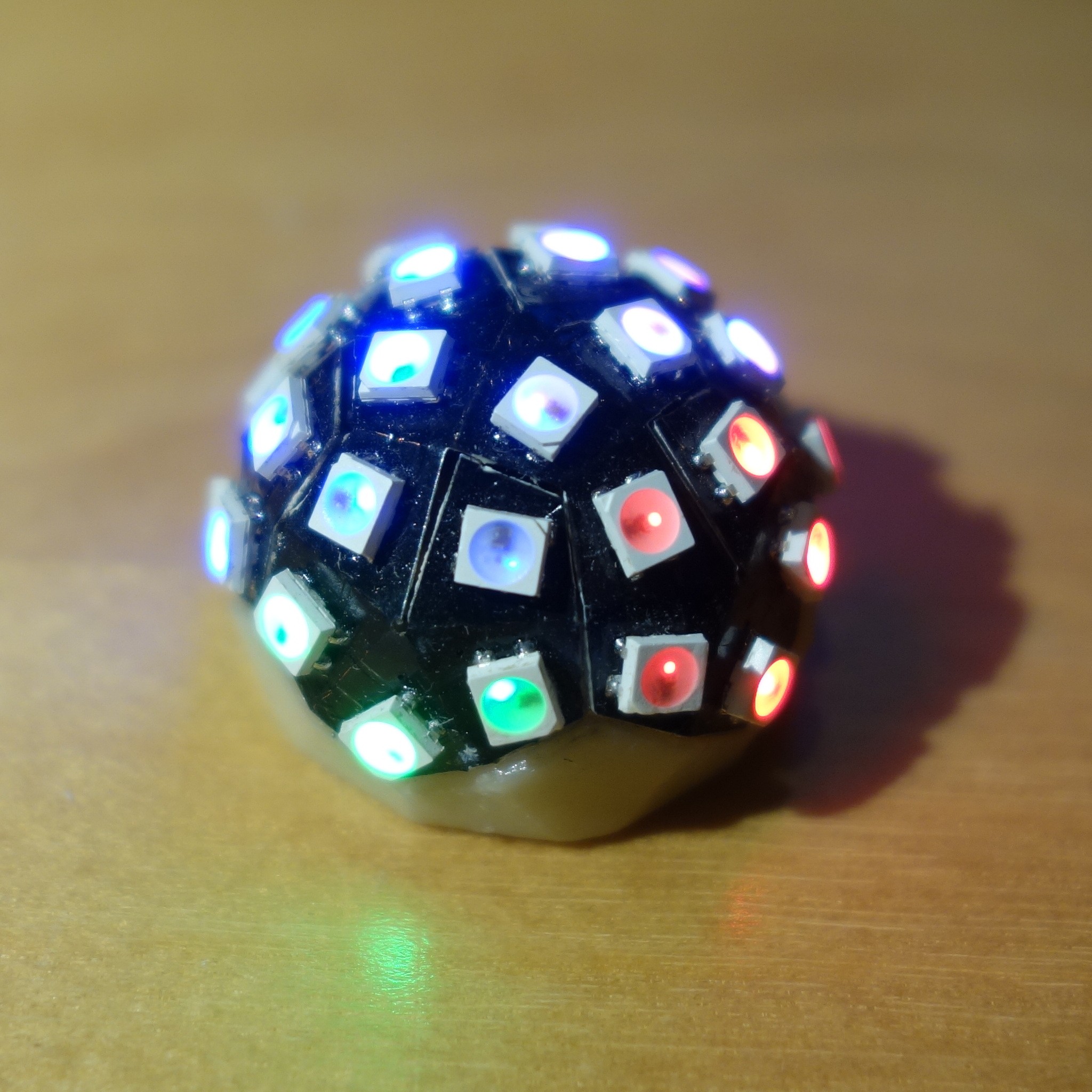
Coin for scale:
Driver PCB v2
For the second version of my led driver PCB I took Travis Goodspeed's Goodwatch Project as a base and added a lipo charging circuit. Since I don't need the LCD driver required by the Goodwatch, and I don't have a lot of space, I chose to use the smaller, but similar cc430f5137 chip. The board is single sided, saving up space inside the ball, and the switch is nowattached to the PCB..
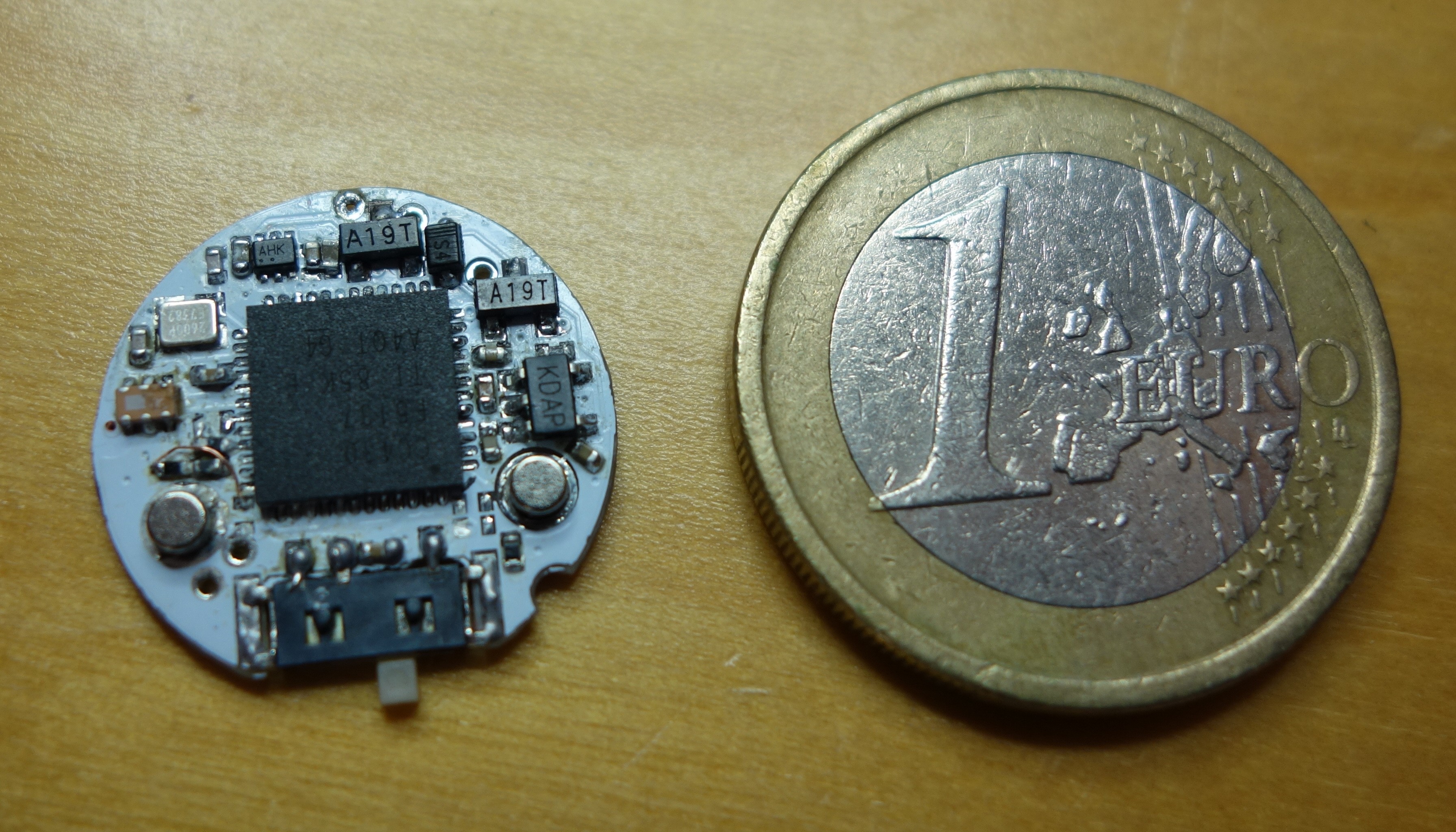
A hand-crafted assembler routine can do realtime temporal dithering while running at 2.4MHz(!), using SPI data-out to generate the WS2812 800kHz waveform.
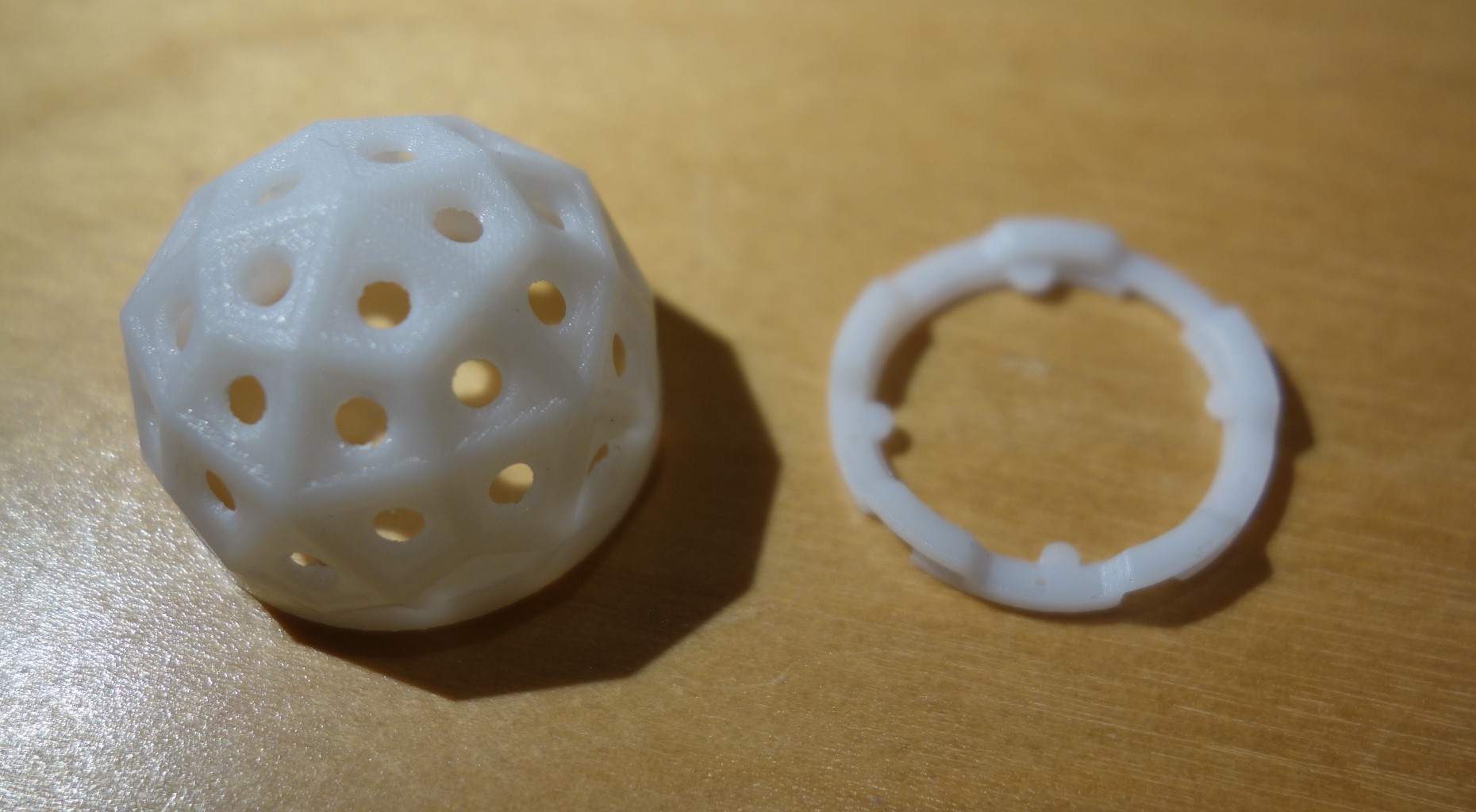
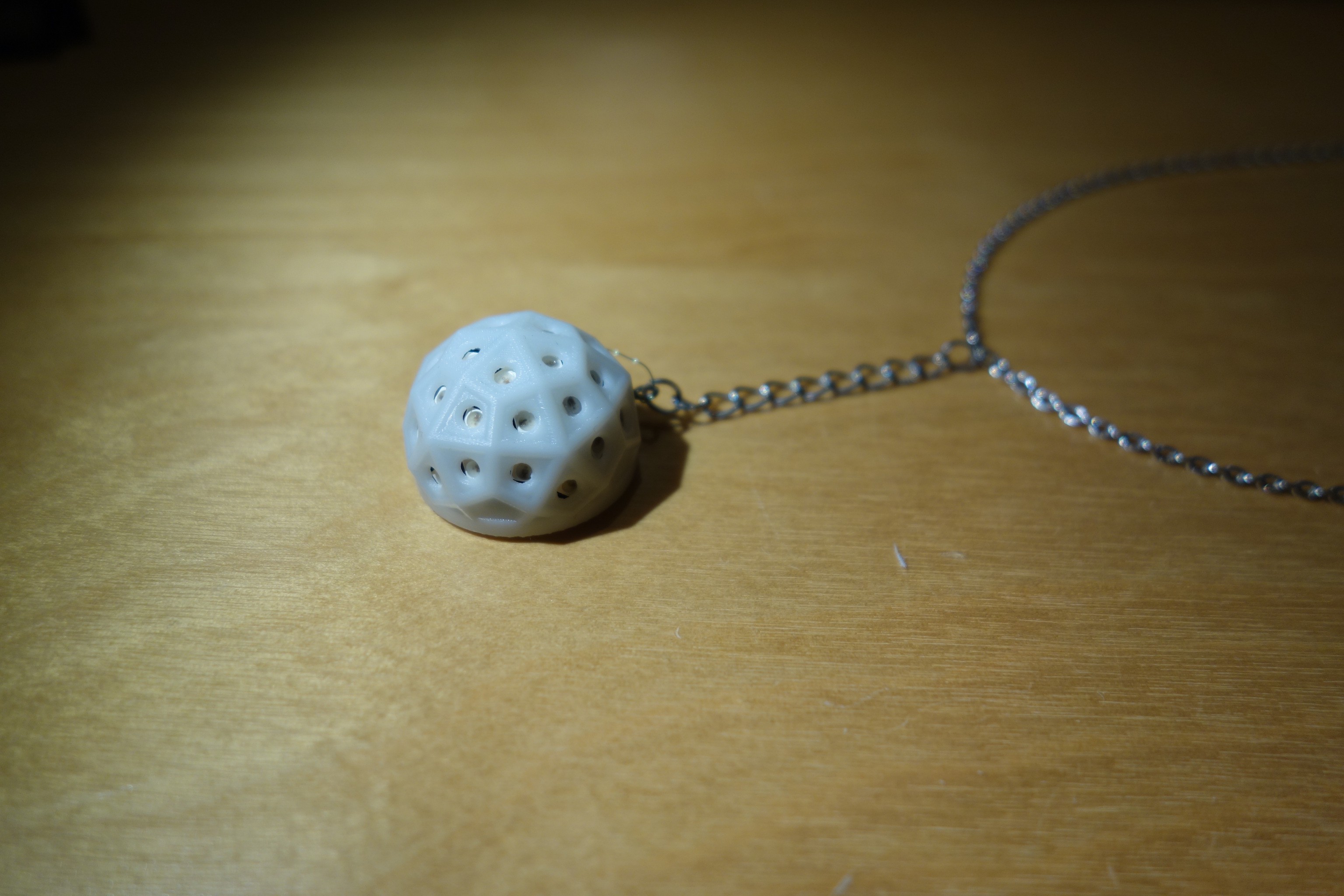
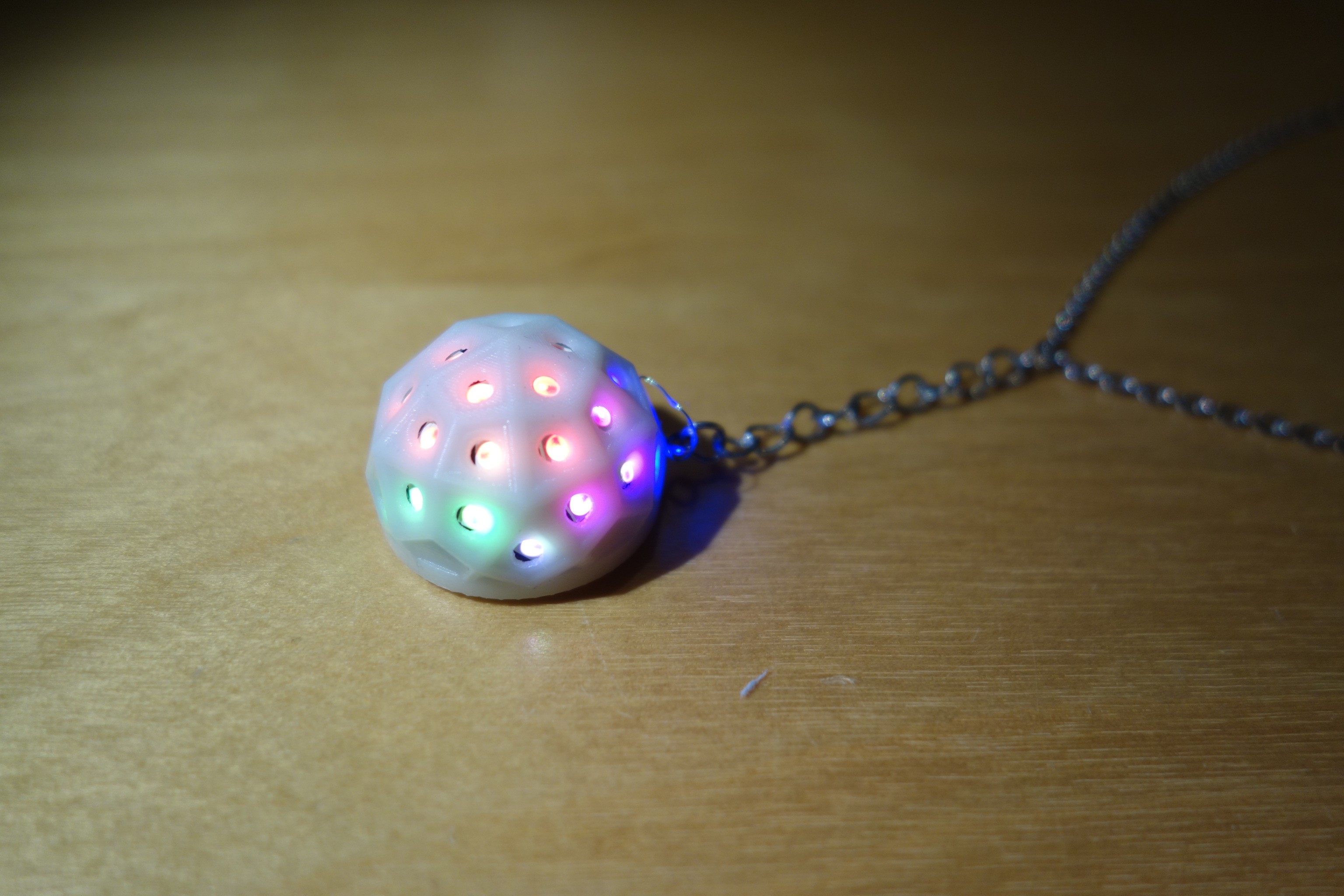
To protect the ball, I designed and ordered a plastic dome, and a ring to fit around the driver PCB. They click-twist into place. (Sadly I got the orientation for the holes allowing the notches to slid into place wrong, so I had to use the dremel for that.)
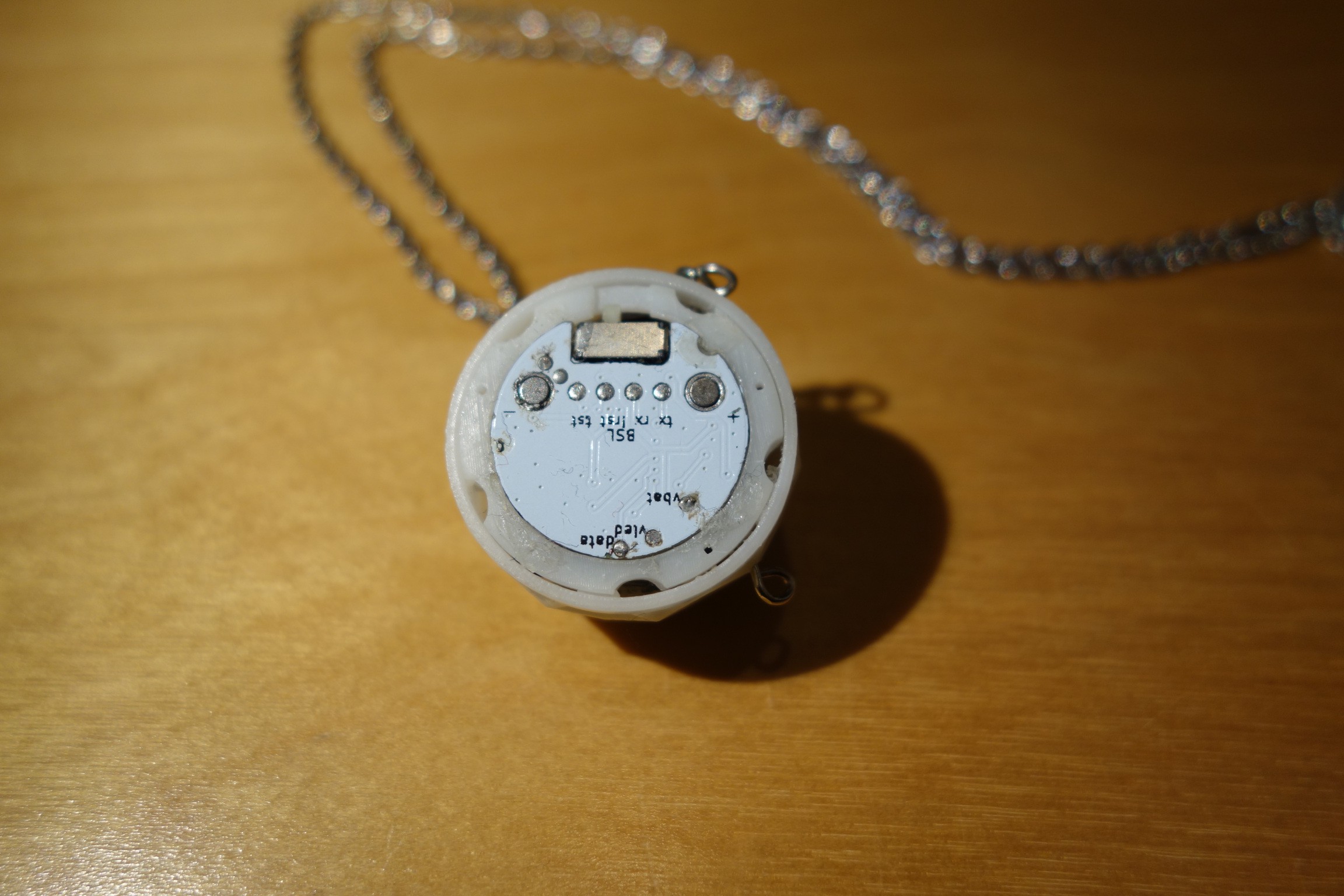
The ball can be charged using a magnet connection and programmed using a 4-pin BSL header.
Final Result
 Erik Bosman