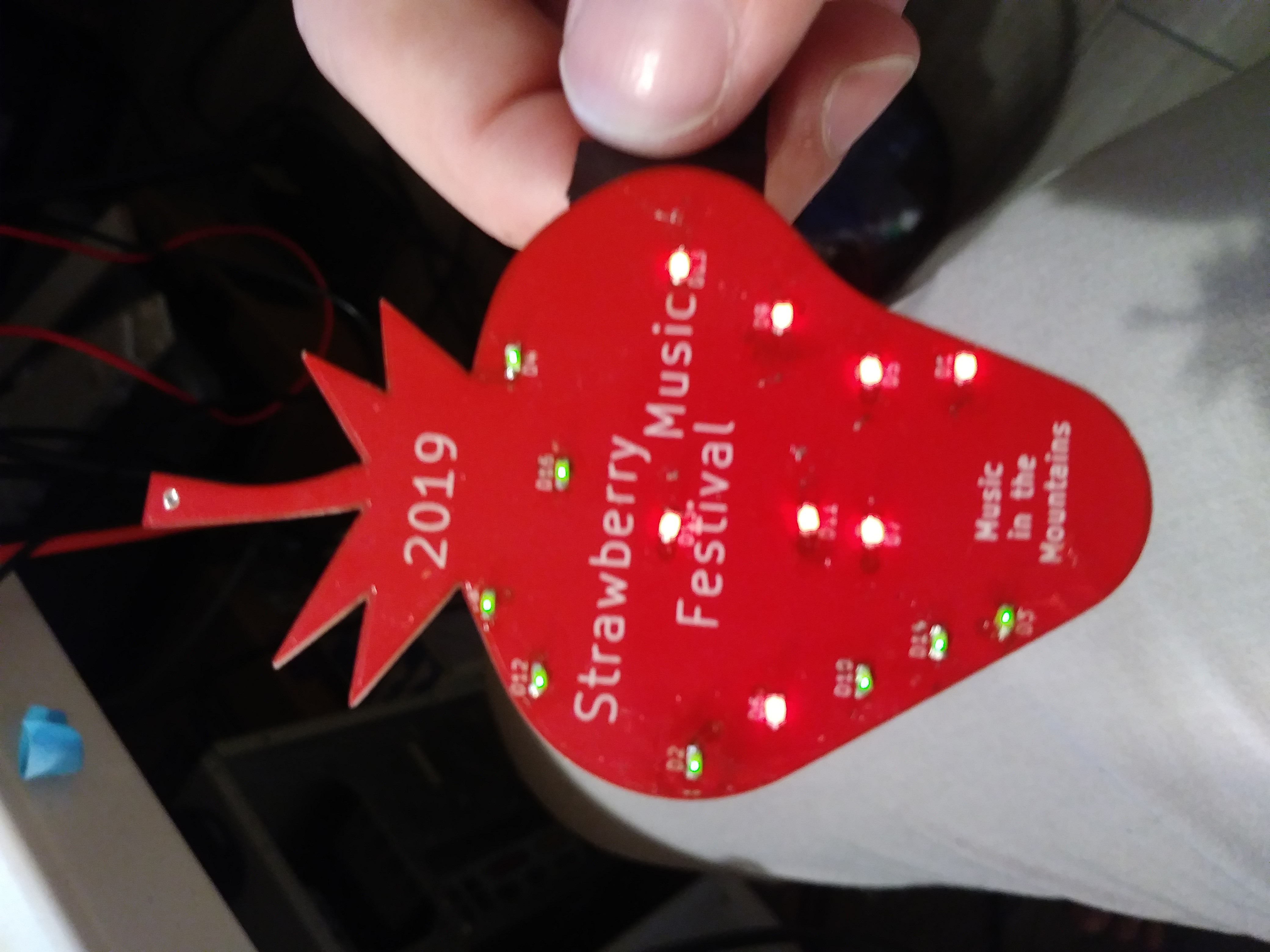
To summarize my failings on Rev B,
- I attempted to reduce soldering time by replacing the 16 LED resistors with 4 resistor networks. I modeled the soldering pads off of the part, not the recommended soldering pad size from the manufacturer. This applied to the power switch I added as well as the a button I added to cycle through animations.
- I made a mistake and reversed the polarity of the SMD battery clip.
Rev C, had repaired the failings with the resistor networks, the power switch, and the battery clip. I was not able to get the spacing on my button correct in this revision.
Rev C was ready for animation development. I hit one shortcoming with my button, that I am still trying to puzzle through. Due to me not being able to get my button working, I was attempting to cycle through animations based on power up. The logic behind my power up solution was to write to one location what animation to currently do on the EEPROM on the PIC18F45k20 and increment it on power up. There is no support for EEPROM on the PIC18F!!! The project was in the eleventh hour when I was attempting to get the EEPROM to work. I eventual conceded to my poor planning and configured timer 3 to switch between animation after a period of time.
I delivered one assembled and one kitted badge to my friends at the Strawberry Music Festival. They were surprised with the gift and happy with it. Fortunately one of them is a tinker and might be willing to update the badge once I get around to fixing the firmware to be more in line with my original image. At this moment in time, it is good enough to wrap up my documentation and open source the project.

 Ian Shannon Weber
Discussions
Become a Hackaday.io Member
Create an account to leave a comment. Already have an account? Log In.