Partly in support of another project I am thinking of starting, which would involve replacing the electronics with my own, I did a teardown of a micro RC car. This one is a “Pocket Racer” brand car. It is interesting looking into the design of such a low cost device (whole thing for $8.)
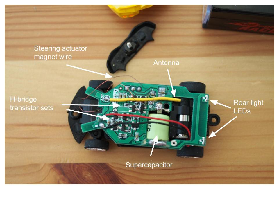
These cars are charged from the controller, which uses AA batteries. In the image below, you can see that the RC car actually does not have a battery itself, but rather uses a supercapacitor, mounted in a cutout of the PCB. This simplifies the charge circuitry, and allows the cars to be charged quickly. The car is rear-wheel drive, with a single small motor to drive it. It does not have precise steering control. Instead, there are only discrete turning options: left, straight, or right. Interestingly, it appears that the steering and drive are controlled by H-bridges made of discrete transistors instead of H-bridge ICs. Presumably this is to lower the cost. It seems the power for the actuators is straight from the supercapacitor. A small piece of wire is used as the antenna. Strangely the steering actuator wires are thin magnet wire. I have not opened up the front of the case where the steering is, but it is likely that there is a simple solenoid used to steer the front wheels. On the back of the top PCB, are two SMD side-view red LEDs, used as reversing lights.

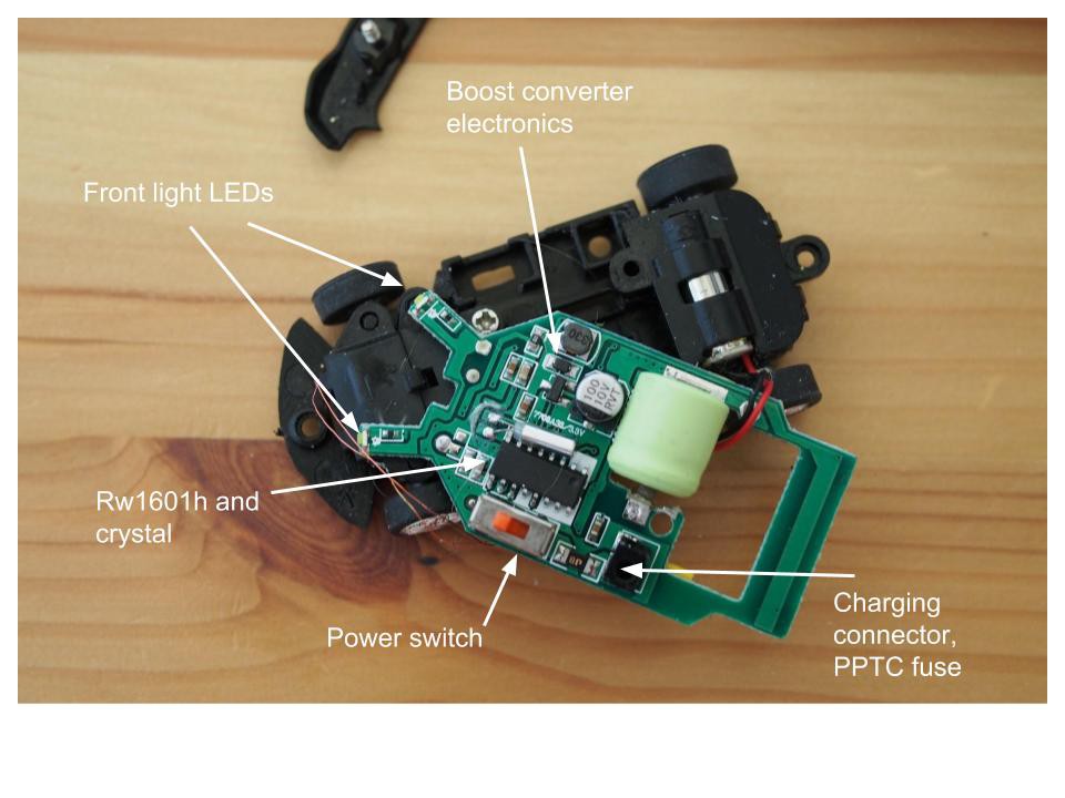
The below image shows the underside of the PCB. On the front, white SMD side-view LEDs act as the front lights. The IC is labelled rw1601h, which seems to be the wireless receiver. I was not able to find details about this part, but Google returns the 434 MHz RF receiver from SparkFun as the first search result: https://www.sparkfun.com/products/10532. Attached to this IC is a can SMD crystal. The power switch is also mounted on the bottom of the PCB. The charging connector is mounted next to the switch, with what appears to be a SMD PPTC fuse. On the other side, there are some power conversion components set up as a boost conveter: an inductor, capacitor, diode, and transistor. The transistor gate is connected to the rw1601h IC, so it appears that component is also handling the power conversion electronics. The supercapacitor charges up to about 1.4V, so the boost converter appears to take the lower voltage of the supercapacitor and generate a 3.3V rail for the electronics.

Overall, it seems it should be pretty easy to replace this PCB with one of my own so I can control this car. I may try running the motor at higher voltage (as others have done to speed them up), and will likely power it using a battery instead of a supercapacitor.
Discussions
Become a Hackaday.io Member
Create an account to leave a comment. Already have an account? Log In.