 Pavel
PavelBuilding the Arithmetic Unit is great, but as it is there is no simple way to assess its workings. As I've built it, I am personally know what to look at, but for most outside people, the shining of the LEDs on the board is still cryptic. Also, by no means it is obvious for me at the first glance. And giving inputs by connecting individual wires is a pain.
So, the solution for this is simple interface, Control Panel (CP) with switches and indicator lights for switch states and output from the circuit to which it is connected.
For each individual switch, there is a simple circuit:
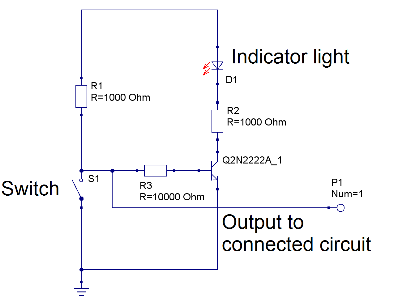
The values of resistors directly connected to the transistor may vary depending on the colour of LED.
I decided to make this control panel look pretty, and for this , it is composed of two boards, one with switches, lights and connectors ("face board"), and other with all transistors and most of resistors ("driver board").
It turned out to be quite a lot of work, because there are so many wires I needed to solder.
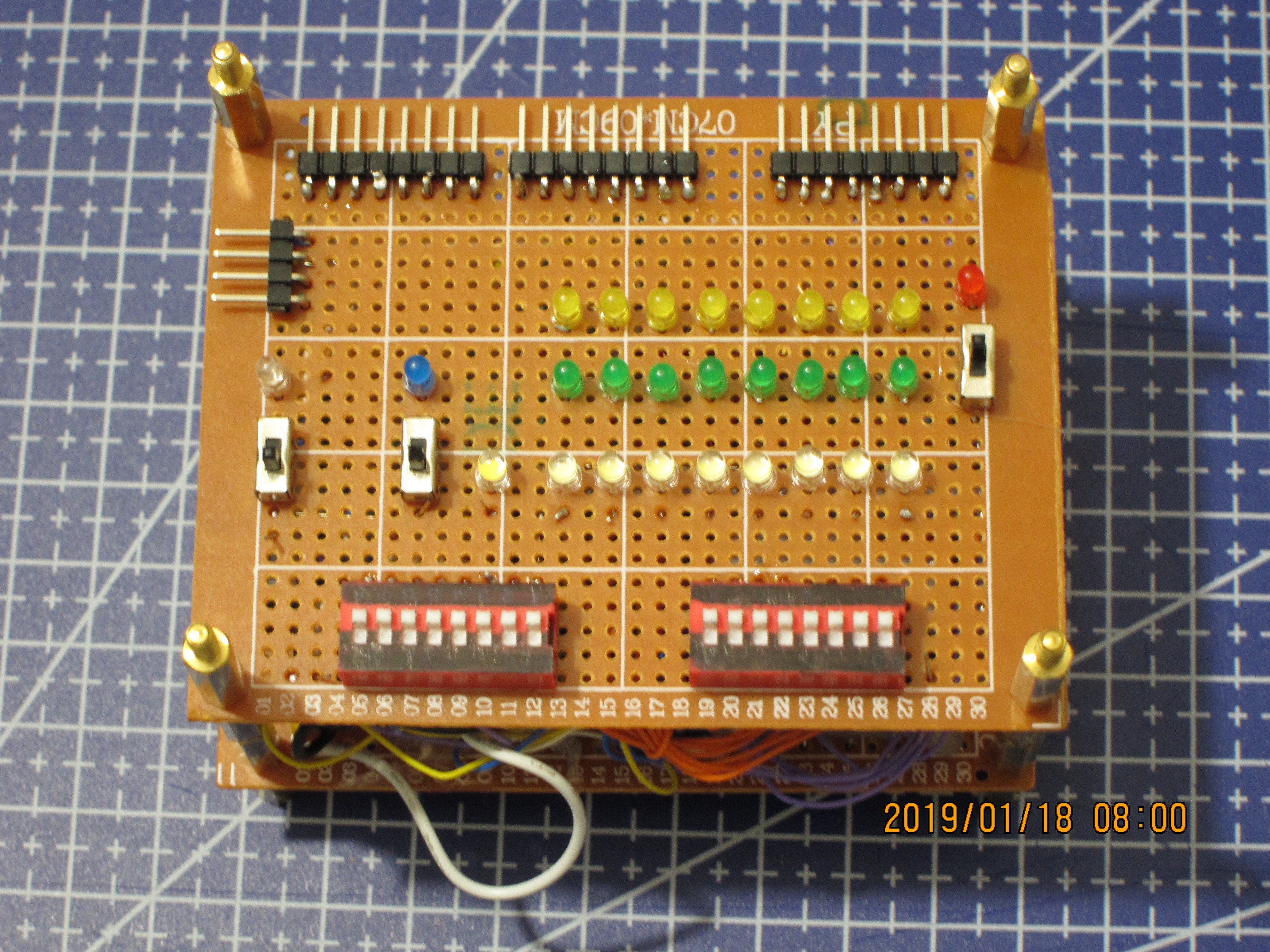
So, here is the "face board":
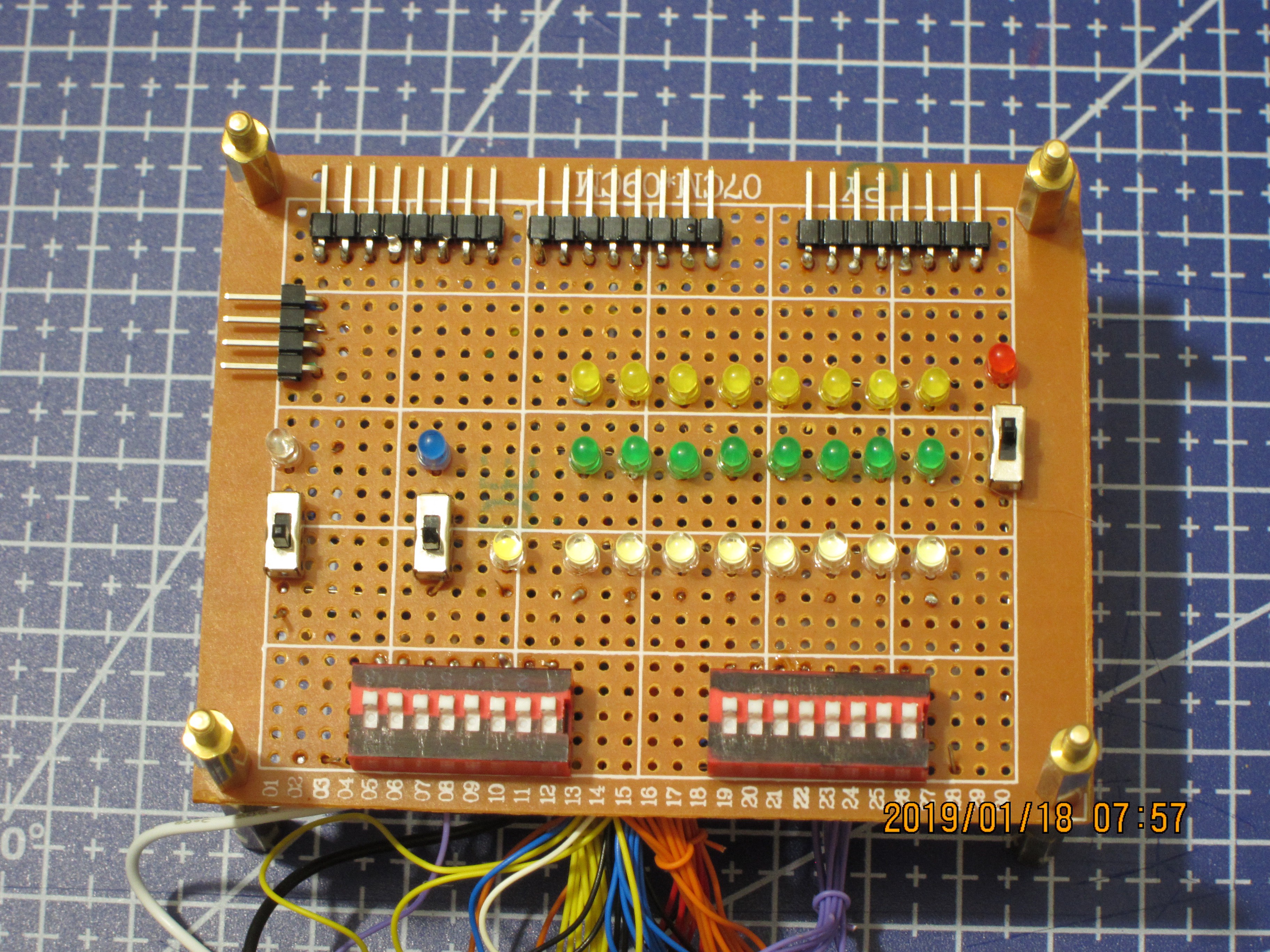
Connectors:
Facing left, 4 pin, signals, from top to bottom: Carry_out (coming to the CP), Carry_in, Carry_in_enable, Sub/Inv B
On the top, from left to right:
8 bit operand A - coming out of CP;
8 bit operand B - coming out of CP;
8 bit Result - coming into the CP.
Switches and associated lights:
Individual switches:
Leftmost, with clear Red LED - Carry_in_enable,
Closer to light rows, with coloured Blue LED - SUB/INV,
Rightmost, with coloured Red LED - Carry_in.
Switch banks:
Left -- operand A, associated with the top row, Yellow, LEDs,
Right -- operand B, associated with the middle row, Green LEDs.
Lights indicating incoming signals -- bottom row, 9 White LEDs:
The leftmost, Warm White, near SUB/INV switch: Carry_out,
The rest 8, Cold White: Result.
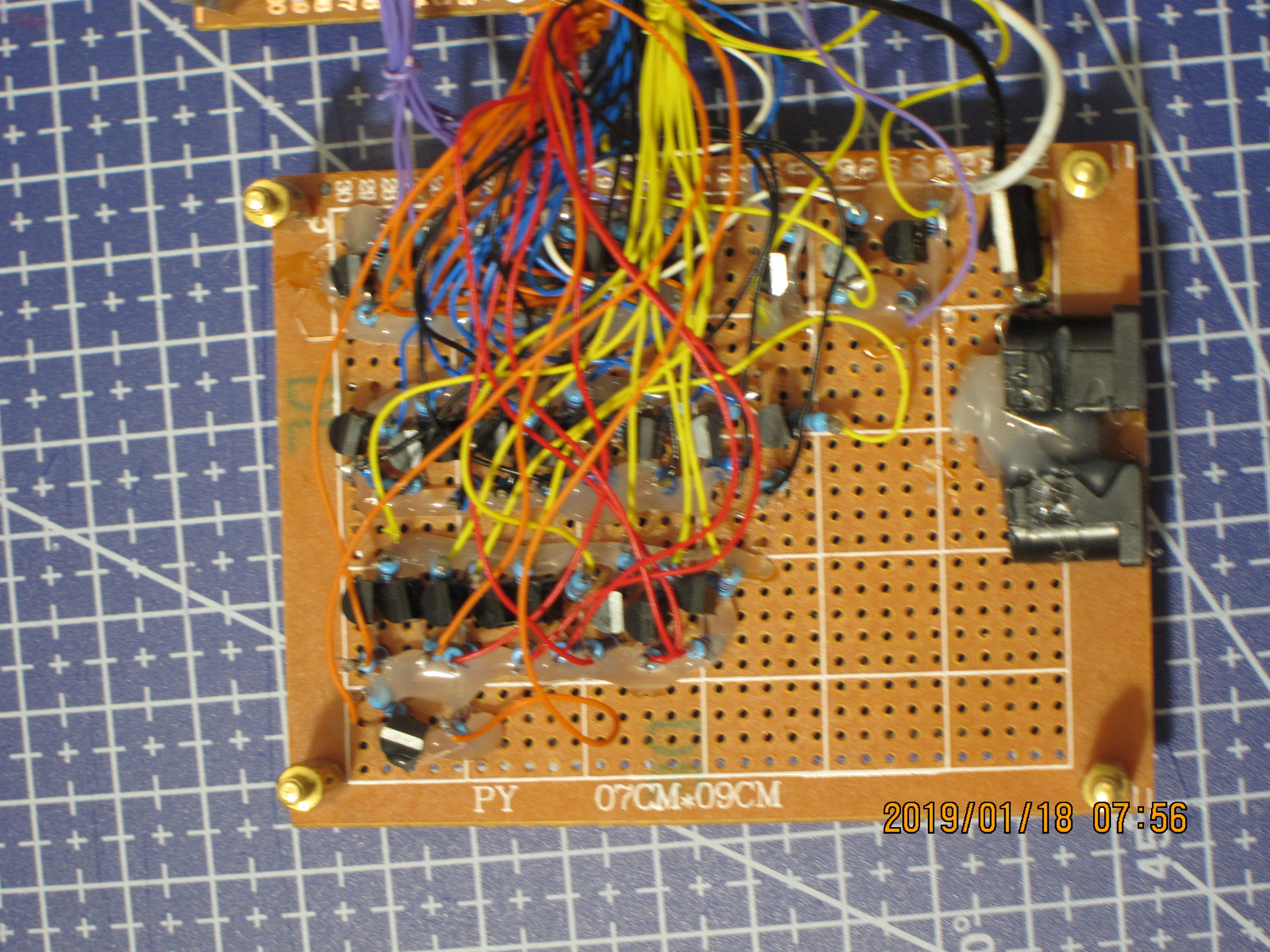
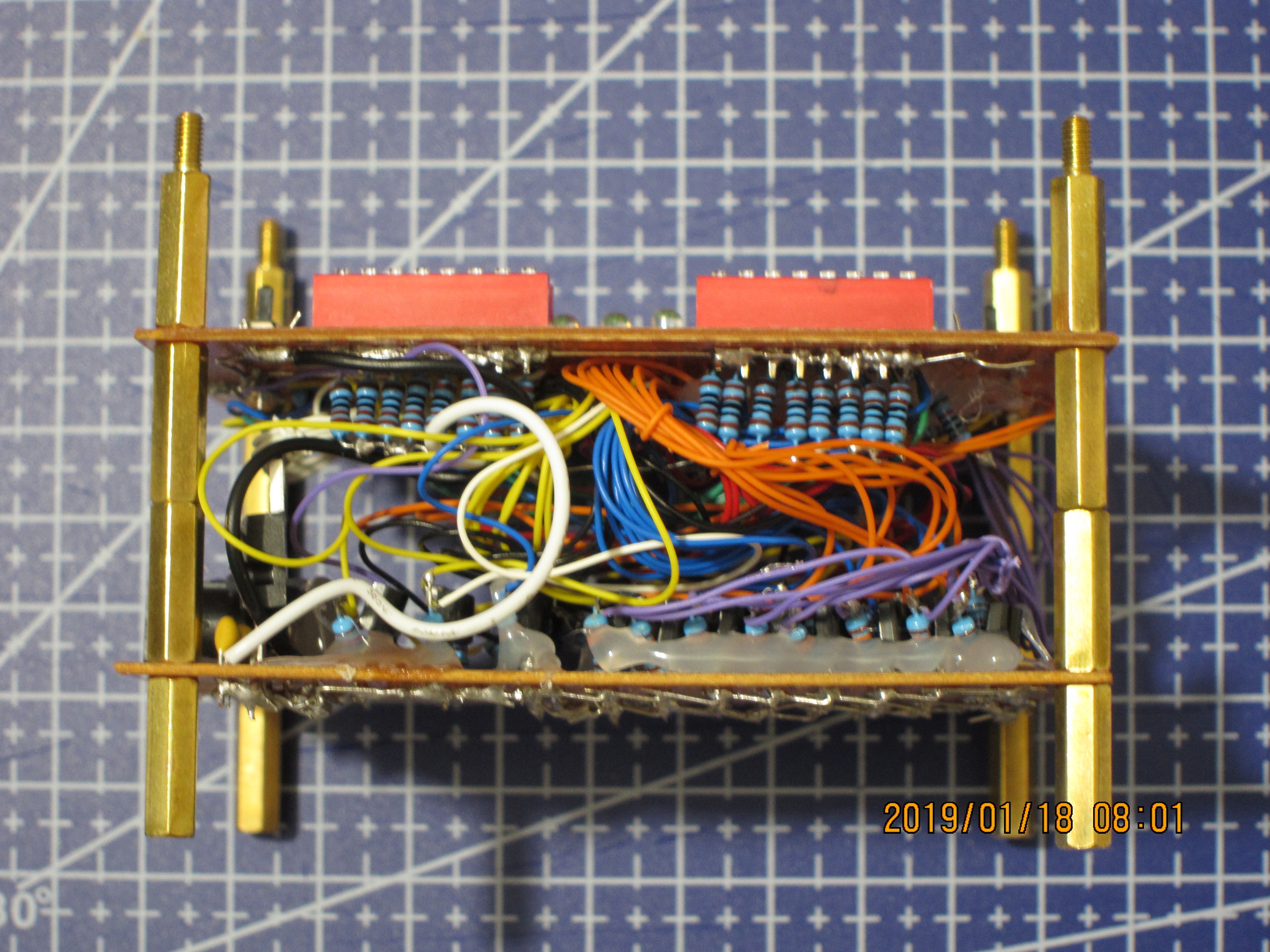
And the "driver board":
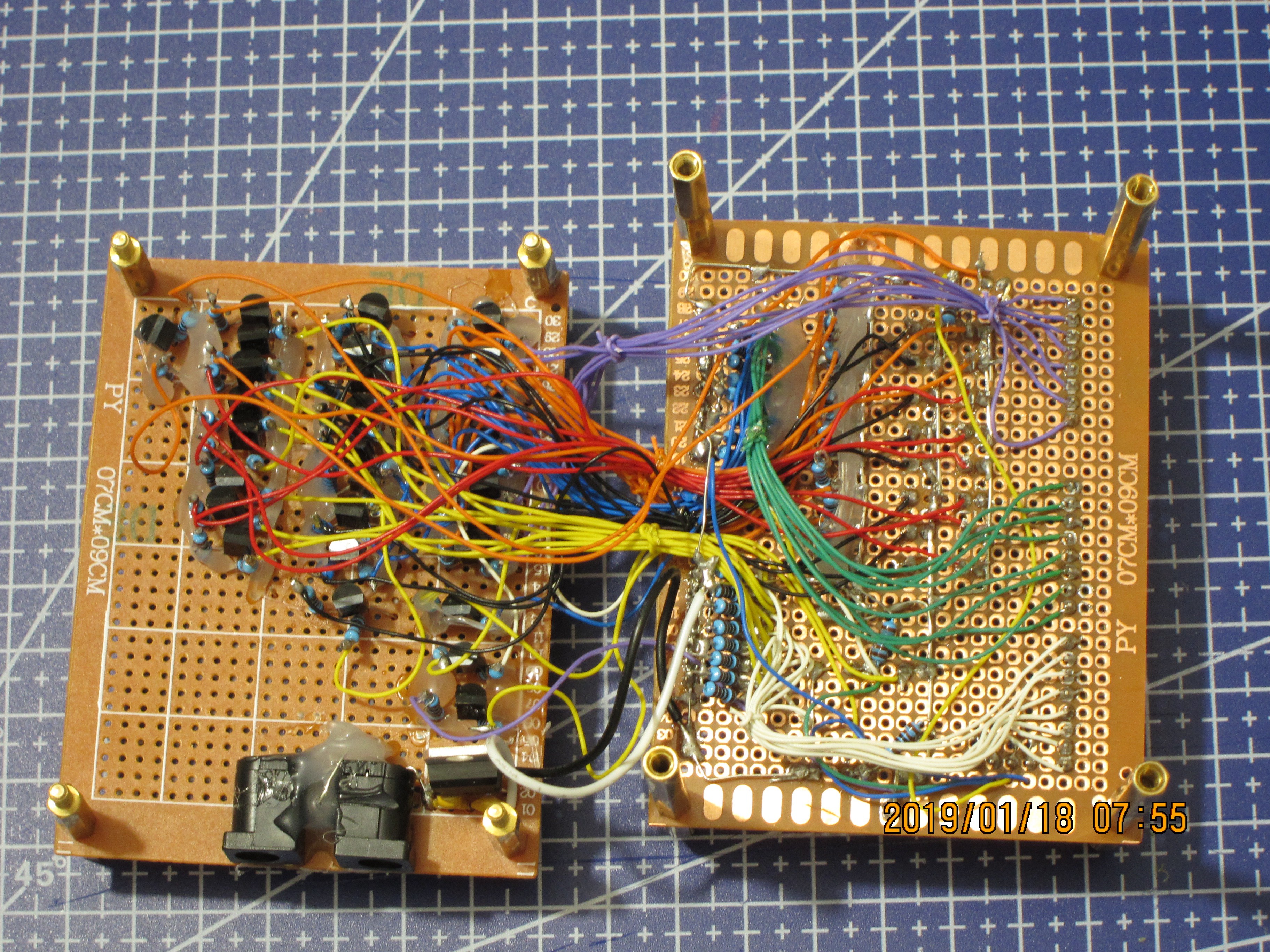
On this overview one can see these boards connected with a bunch of wires:
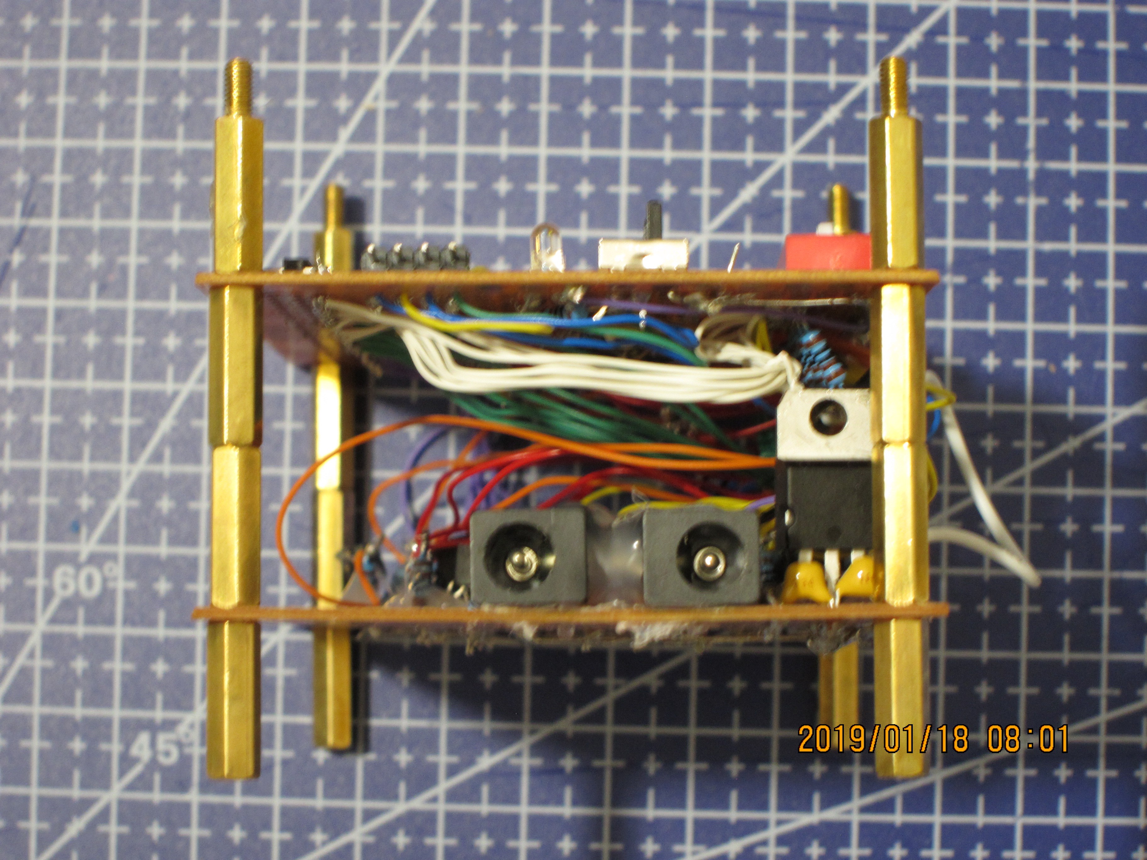
When the boards are stacked, it all looks prettier:
View from the sides:
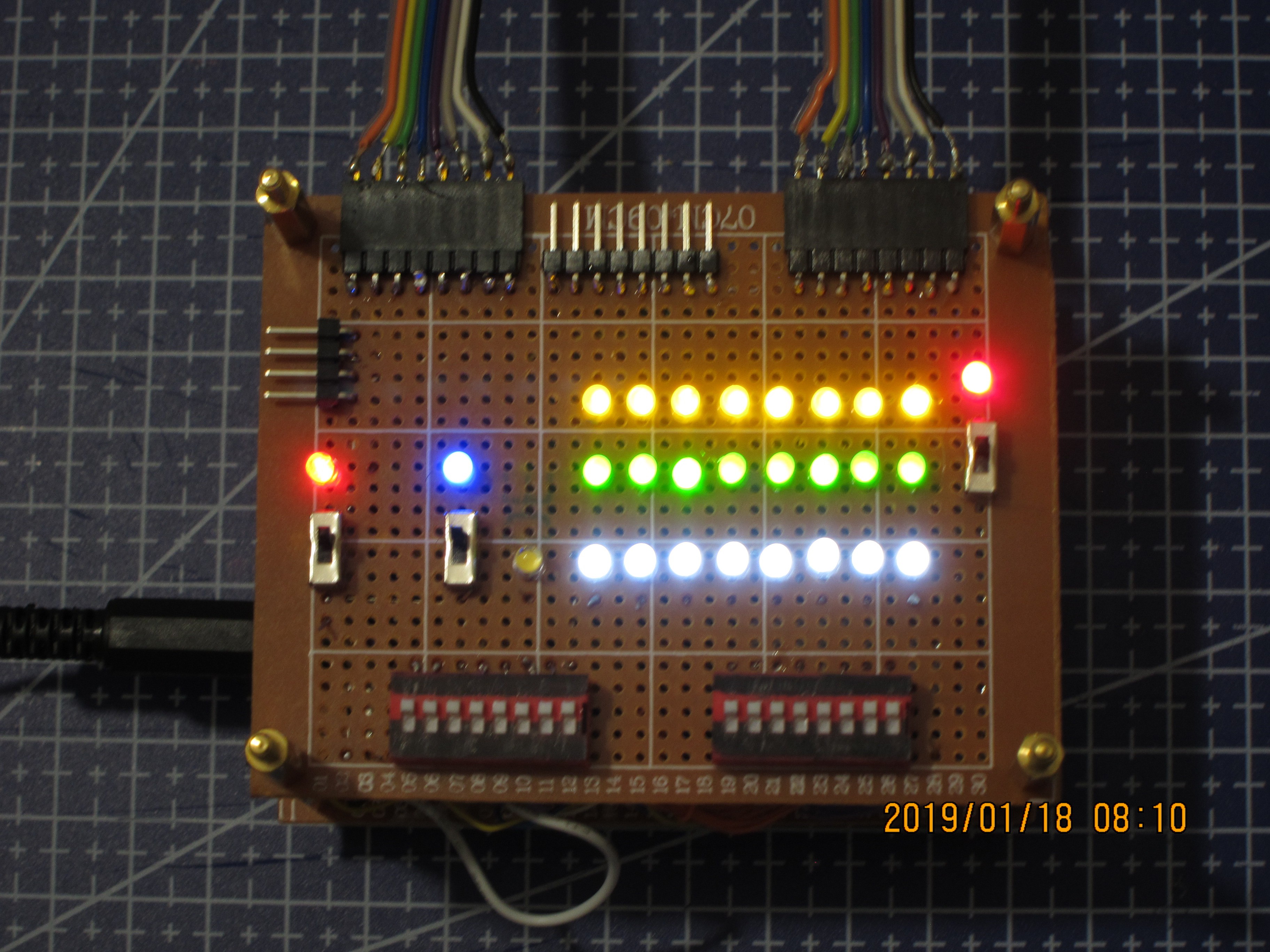
Testing all the lights (except for C_out):
After all the teasing, below there are image of this Control Panel connected to the Arithmetic Unit:
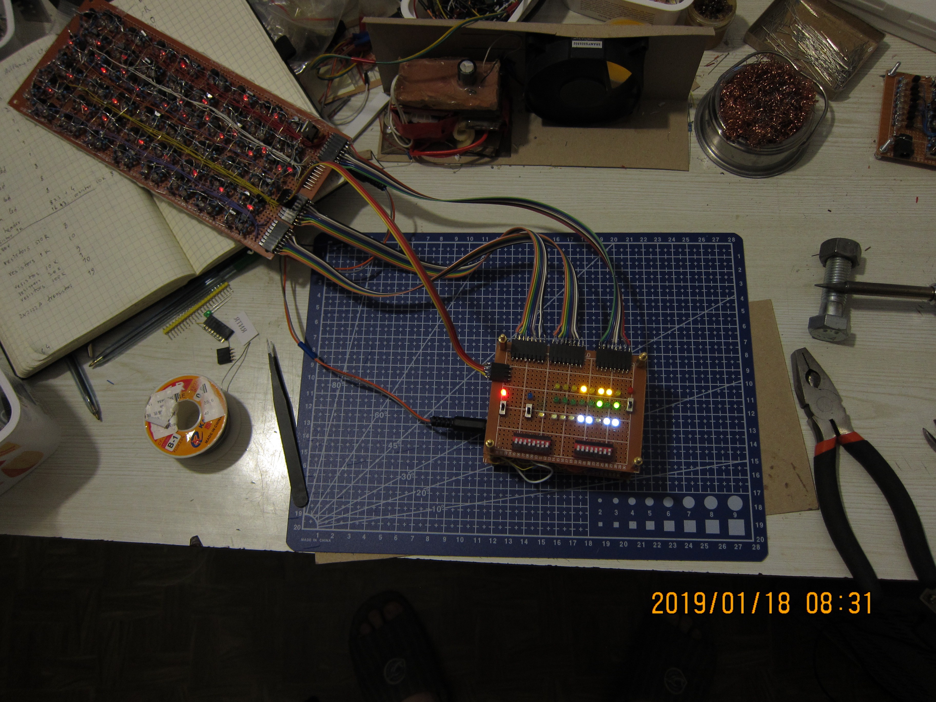
And the video showing how it all works together.
Total parts count for the Control Panel:
| Part name | count |
|---|---|
| Perfboard 30*24 holes (9*7 cm) | 2 |
| 2N2222A npn transistor | 19 |
| Resistor 510R | 8 |
| Resistor 1k | 28 |
| Resistor 10k | 17 |
| Resistor 20k | 1 |
| Resistor 100k | 10 |
| Red LED (clear) | 1 |
| Red LED (coloured) | 1 |
| Blue LED (coloured) | 1 |
| Yellow LED (coloured) | 8 |
| Green LED (coloured) | 8 |
| Warm White LED (clear) | 1 |
| Cold White LED (clear) | 8 |
| SPDT switch (connected as spst) | 3 |
| DIP bank of 8 SPST switches | 2 |
| L7805 Voltage regulator | 1 |
| Capacitor 0.1uF | 1 |
| Capacitor 0.33uF | 1 |
| Pin headers x8 | 3 |
| Pin headers x4 | 1 |
| Power connector | 2 |
| Total parts | 127 |
Discussions
Become a Hackaday.io Member
Create an account to leave a comment. Already have an account? Log In.
Nice system :-)
One step further would be to have hexadecimal encoding and decoding.
BTW : 7 transistors can be replaced by one ULN2003 :-)
Are you sure? yes | no