It was about the time to make a decent preamplifier for this audio amp. It's a two channel op amp circuit with in a non-inverting mode, with simple 1st order RC filters. Opamps have fixed gain of 6dB (Av=2) each, and the level is adjusted by simple potentiometer.
I've assembled second board and now I can play with the stereo sound :)
I also brought it to a friend's house party and it was pretty cool to see (hear) it in action in a room full of people. It really did deliver a high quality sound. Now I really need to start wrapping it up and make a nice furbished housing for it.
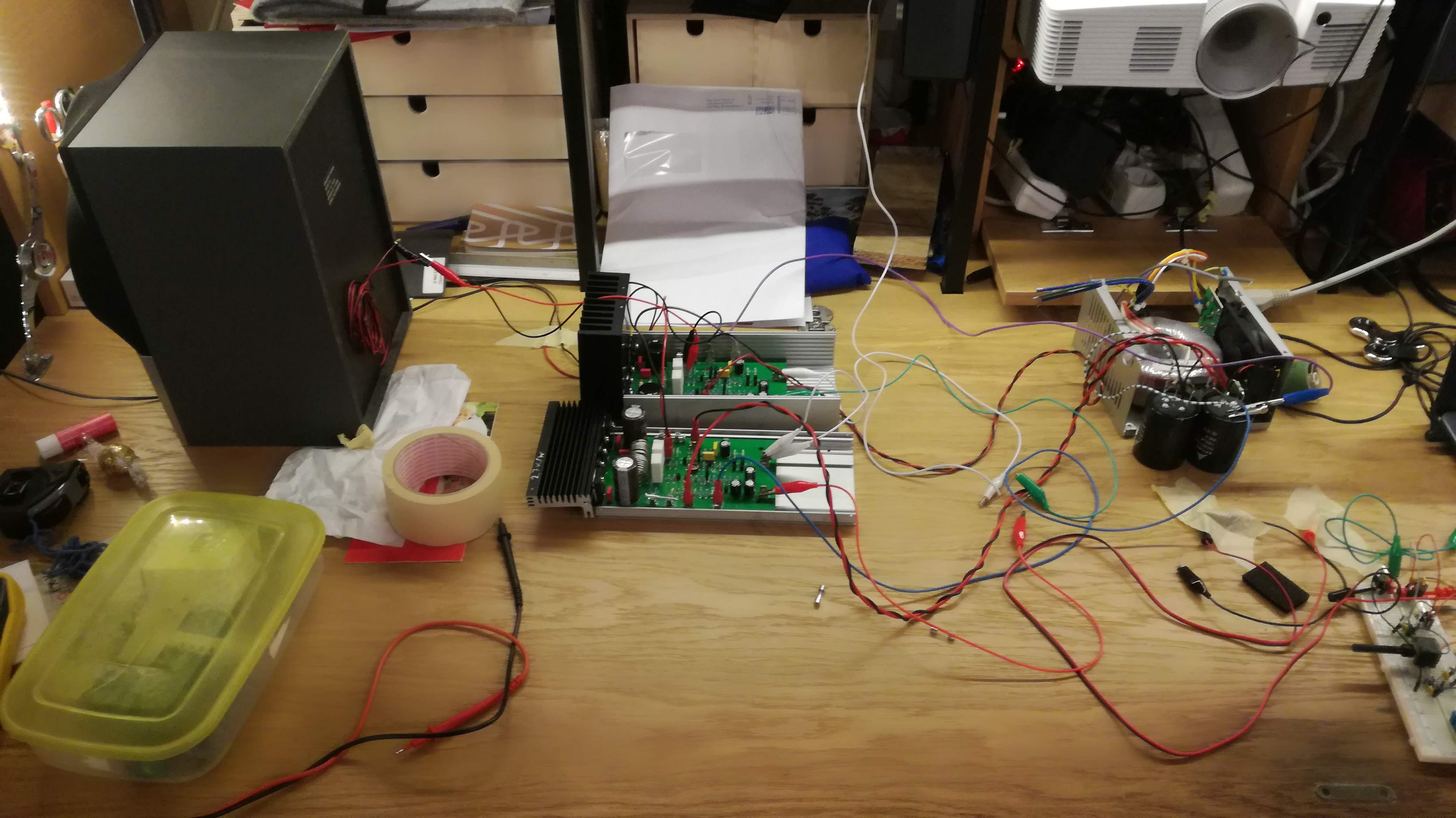
What would be an audio amp project worth if we weren't playing some music on it. I hooked up my newly acquired cheap loudspeakers and the best type of preamp (a single potty) and got some crystal clear sound out. No humming, no distortion, no screeching. Not even those sound blasts during the power up. Even my more audiophilic friends said the sound is pretty good. Here's some screenshot from Rigol's scope.
---------- more ----------
For the first try, this made me quite happy. I'm not sure how good it really is, but I guess in some time I'll need to find a quality audio test equipment. So far, I'm only having fun building it.
All this time, I was powering my amp using +/-30V/5A Rigol power supply. Obviously, this is not something permanent, and I'd need to build a separate power supply. Since I'm striving for the Hiest of Fies, switching mode supplies are out of the question. This means a big ass transformer.
Previously, I have calculated that I need 120VA source power, but then I thought to myself, why? Yeah, the idea was to build a high power amp. But, let's be honest, I will probably never use it. During the sound test, I found out that even a couple of Watts is already to loud for my delicate ears, and 100W capable speakers are heavy and expensive, I decided to lower down my power expectations. How much? As much as my easily obtained trafo can give :)
So, in my company's scrap room, I got nice toroidal, bipolar 19.5V/2.6A transformer, perfect for my project. This translates to 101.4VA output power, and with the efficiency of 66%, I can expect some 66W output power. Not bad for saving an effort of buying an expensive trafo. And with a notion, that design is easily applicable for higher supply voltages, if I ever find a more powerful trafo. Anyways, I dug out some bridge rectifiers and thick elkos, and contrapted myself a lovely little full-wave rectifier. I was lucky to find some 4500uF caps, so power demands should be satisfied.
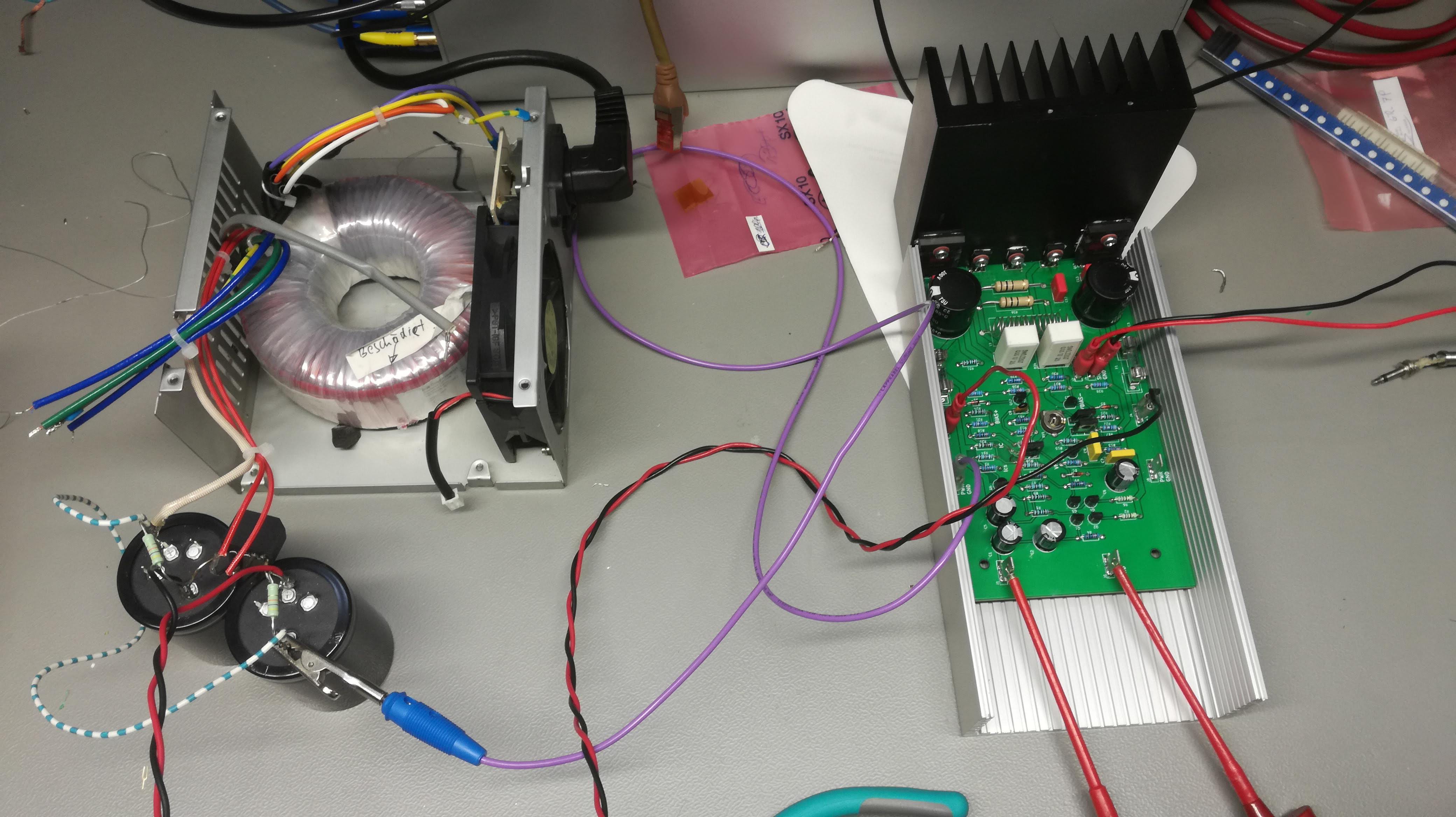
Here you can see the power supply I've built. The trafo has a sticker saying 'beschädigt' meaning it has some insulation damage probably due to the fall from the table. Nothing I couldn't fix with a nail polish. I've put it in an old ATX housing, which is fortunate cause it already contains all necessary power filtering and PTC protection (small board next to the power inlet). I haven't made a dedicated board for caps and rectifier, so it just sits in the air now. I'll think of it when I build a final enclosure. On top of that, I've put some 20k resistors in parallel with caps (it's always a good idea to put some bleeding resistors when using such huge caps).
In the meanwhile, I'm off to build some preamps and, ofc, the left power channel.
I've found a cheap loudspeaker which I could use to test my amplifier. It is 8 Ohm/50W speaker, so not exactly what I designed my amp for, but it was cheap and worth trying out preliminary tests.
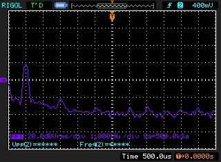
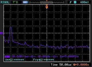
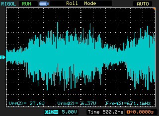
When I plugged it in, and powered the amp, I could see somethin weird. On top of my clean sinewave, there was some kind of parasitic hf signal, not seen before. When I zoomed in, I could see it is a 3MHz component.
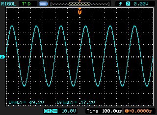
Zoom in on HF glitch:
At first I was confused - where did this come from? Can the speaker introduce some resonance into the amp. Why is all of a sudden so instable.
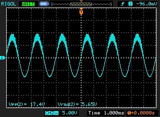
Then I remembered that high frequency oscillations usually originate from low value parasitic L and C elements. And one serious parasitic capacitance between BJT base and collector usually contributes to the amplifier instabilities. As someone here on Hackaday said in comments, these kind of oscillations are preventale by the proper bias of the output stage. Indeed, when I turned the potentiometer, I could see the oscillations going away. Amazing!
Now, I plan to make a simple pre-amp to test some serious music on this loudspeaker.
Instead of loudspeaker, it is better idea to try the amp out with lower cost power resistors. Luckily, in my spare parts room, I've found some of those thick 30W resistors with a nice golden colored casing, I've combined them together to 4.7 Ohm and 9.4 Ohm load and powered the amp on. I was still using Rigol DP832A bench supply at +/-30V.
---------- more ----------
Nothing has burned.
Relief exhale.
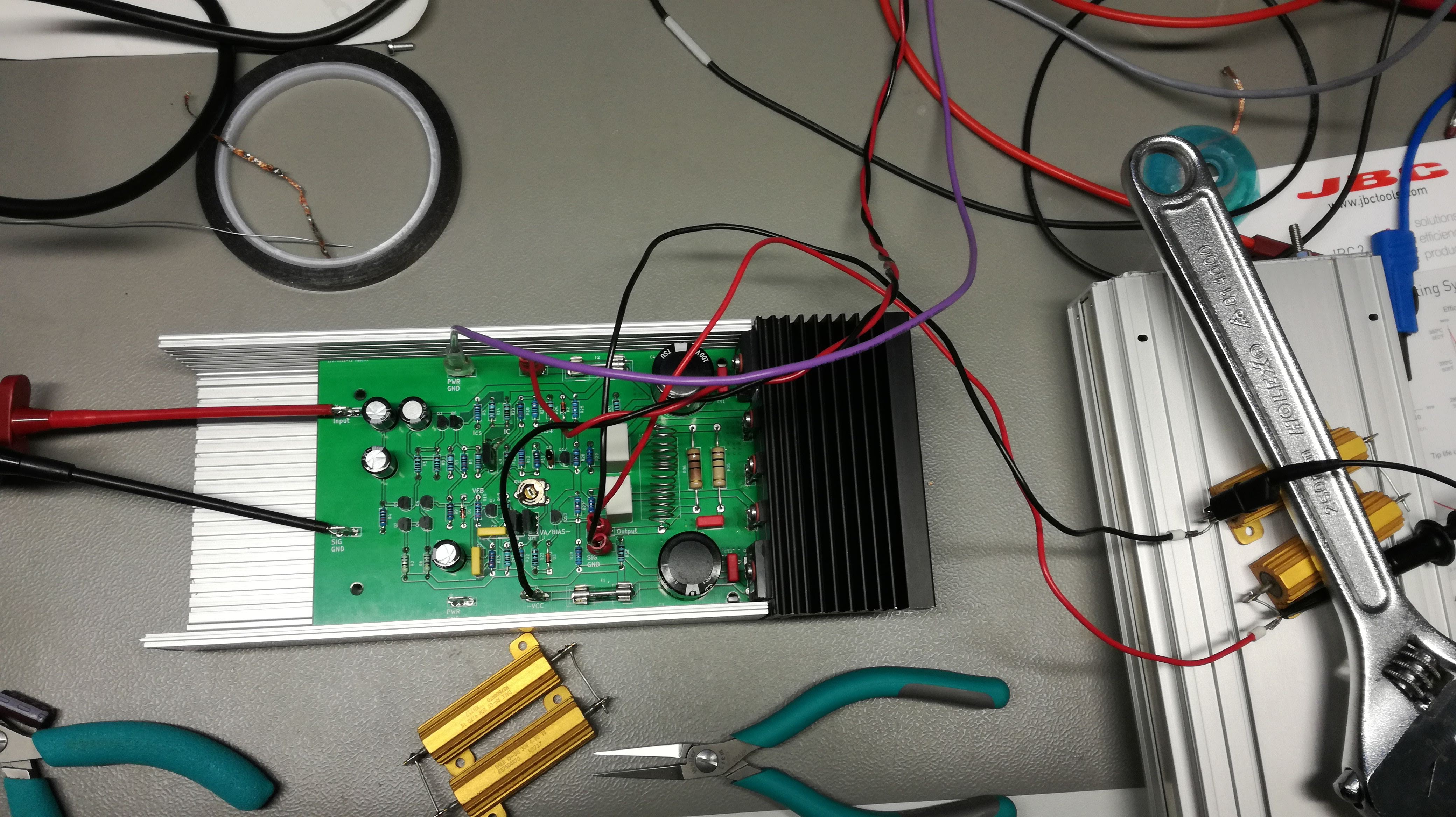
Good, now I could continue analysis. I got max 50Vpp output before clipping started. Meaning that minimum 30 - 50/2 = 5V was needed for each Vce to keep working. I wonder if this can be reduced through increased biasing. EDIT: I've tried it. No, it can not.
Corresponding RMS value was 17.5V. On 4.7Ohm load, this means 65W output power, or 3.7 A rms output current. Having in mind that power supply was feeding 52W on each side, the efficiency is bit above 60%, similar to what was estimated earlier.
Each transistor dissipates cca 20W and this made my heatsink pretty warm really quick. I found some 2.7K/W heatsink in the workshop, but apparently it wasn't good enough. A colleague told me it's 2.7K/W per meter, while I had cca. 10 cm in length. Oh, well, going to find me a better heatsink.
Spectral performance was somewhat worse than expected. I could see some noise on peaks of the sine waveform, and spectrum showed some harmonics. I wonder if this was because of purely resistive load or sign of some design downfall. Further experiments will show if there THD as low as 0.001% is possible.
Apparently everyone in the world knew that 2SC3281/2SA1302 are most likely fakes. Toshiba doesn't produce these as of the year 2000 and originals are nowhere to be found. Again, ESP has a beautiful post about debunking counterfeits: http://sound.whsites.net/fake/counterfeit-p2.htm
Following the advice of many good people on Internet, I went on and purchased MJL3281/MJL1302 by On Semiconductor, from a reliable source (RS). This morning, I've tested the circuit with the new transistors and it worked like charm! Next step, finding a 100W speaker and testing out power performance.
After assembling output power stage, things went wrong. Somehow, I managed to burn high power transistor Q16 (2SA1302). After plugging in the circuit to +/-30V, my bench power supply indicated shorted and I knew immediately that something's wrong. After turning the power off, I measured 0Ohm between pins of the Q16. It was dead. For some reason all other transistors were well and alive.
I stared at the symbol, schematic and layout for one hour. I could't see any obvious error. Could it be that I just received bad chips from ebay?
As a comfort, here's a nice photo of the fully assembled board:
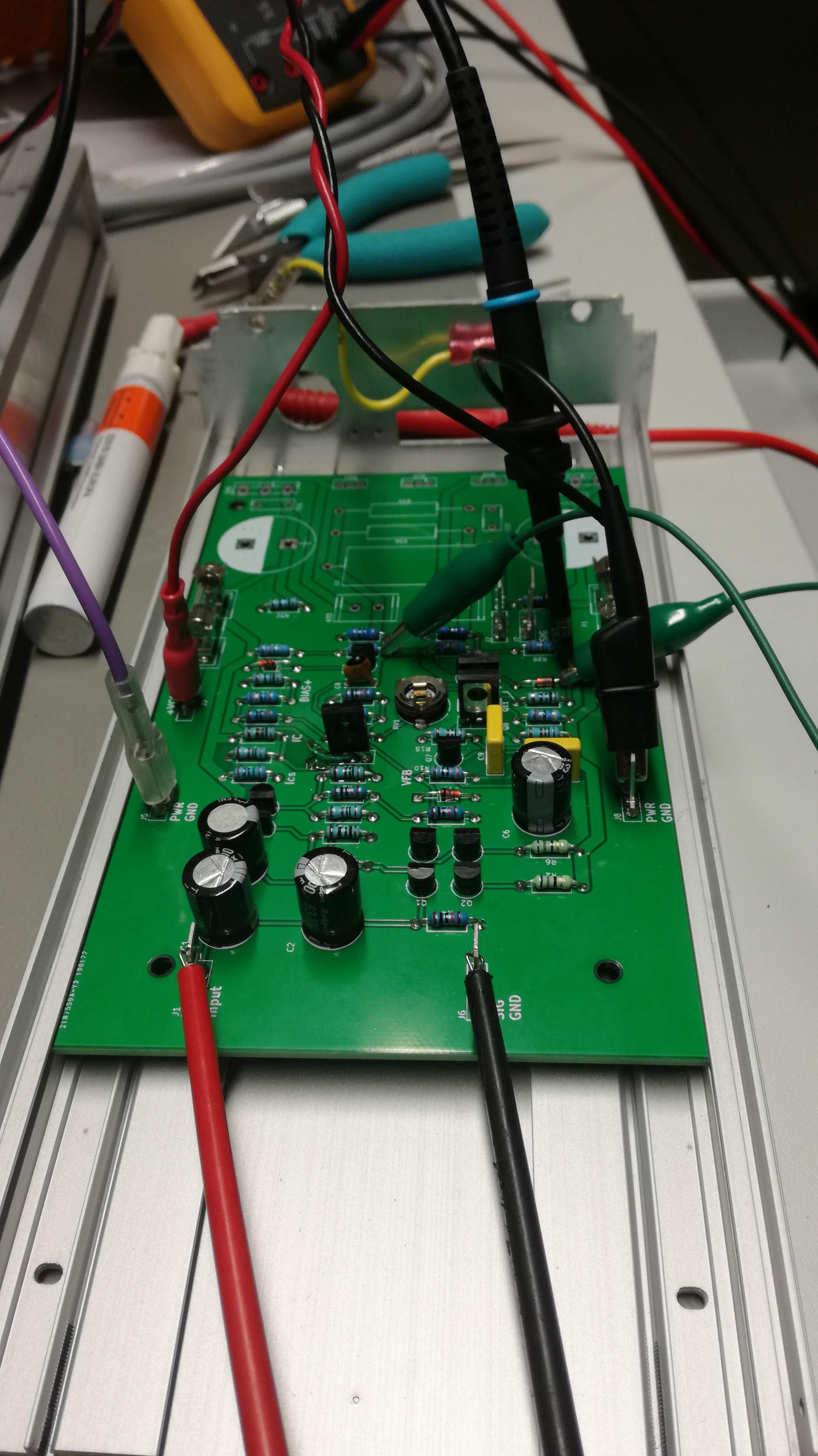
I assembled the Amplifier board up to the power stage. Why? Before plugging high current in, I wanted to make sure that circuit is stable and nothing will burn when I power it on. I found a bench power supply that can deliver +/-30V (Rigol, two channels, forgot the model name), a function generator (also Rigol) and an oscilloscope (you're right, a Rigol one).
---------- more ----------
Before plugging a sine wave at the input, I needed to check DC situation. Are there any shorts? Are the current mirrors working as they should? Is Darlington overheating or something? Luckily, all was fine. Joking, it wasn't. As someone pointed out in comments, I reversed Q9 collector and emitter in the schematics as well as in the layout, which made a current source for VA inoperative. Somehow it mirrored into the current source for Diff Pair which also didn't provide current as it should.
Fortunately, TH components are relatively easy to perform surgery on, so I managed to swap the pins (it wasn't enough to flip the transistor, some trace cuts were needed). Afterwards, everything was fine. Currents were 4mA and 6mA on each CS branch, and Diff Pair equally took 2 mA each. So, that was nice. I also measured 100mV input offset, what is within the expected range.
To check the dynamics of the amplifier, I needed to close the feedback loop somehow. Because the output stage was not populated on the board, I shorted collector of Q11 to the R11, thus providing a feedback from the output. This makes sense, since the output of Q11 is actual output voltage of the Amplifier - the power stage doesn't change the voltage gain.
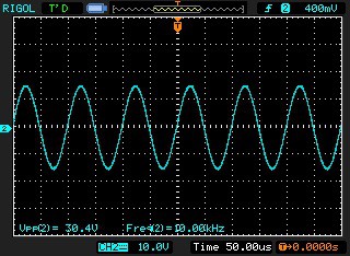
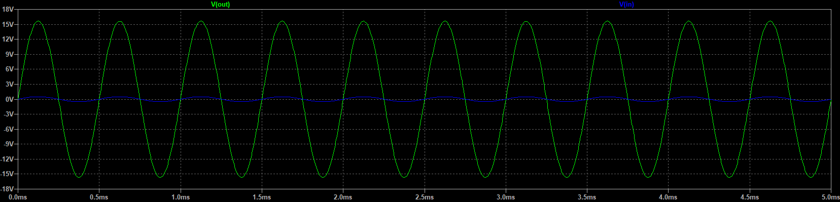
Feeding a 1Vpp sine signal to the input gives a 30Vpp output. Just as expected with the voltage gain of 30 dB.
Beautiful sine wave. I also took a look at FFT, since Rigol scope is powerful enough to crunch the numbers.
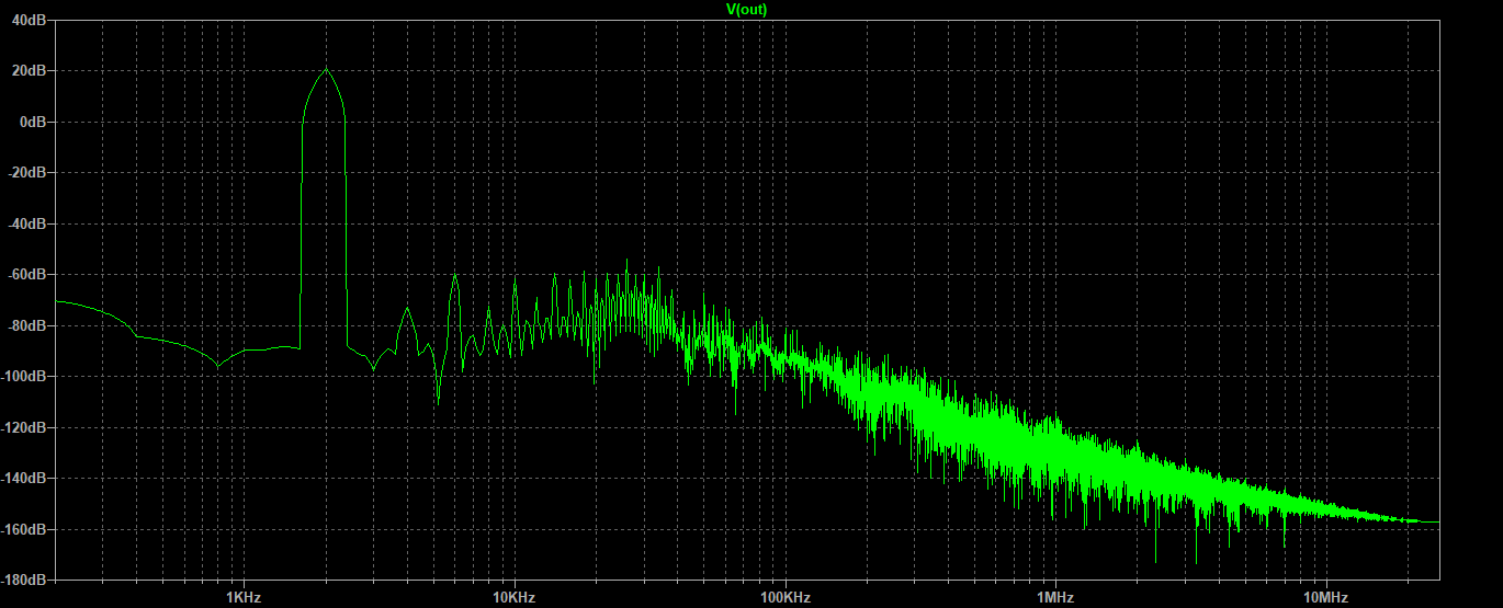
The peak at 1kHz is around 20dBV. Does it make sense? 30Vpp has 10.6V rms. This corresponds to the 20dBV, so, it's all ok. Apparently there is 40dB free range between the basic signal and 3rd harmonic. I don't know if that's too much or I drove my input signal a bit too hard.
Similar happens for a 10 kHz input signal. And any other audio frequency I've tried. I think it's safe to say that amplifier's stable and it works as expected.
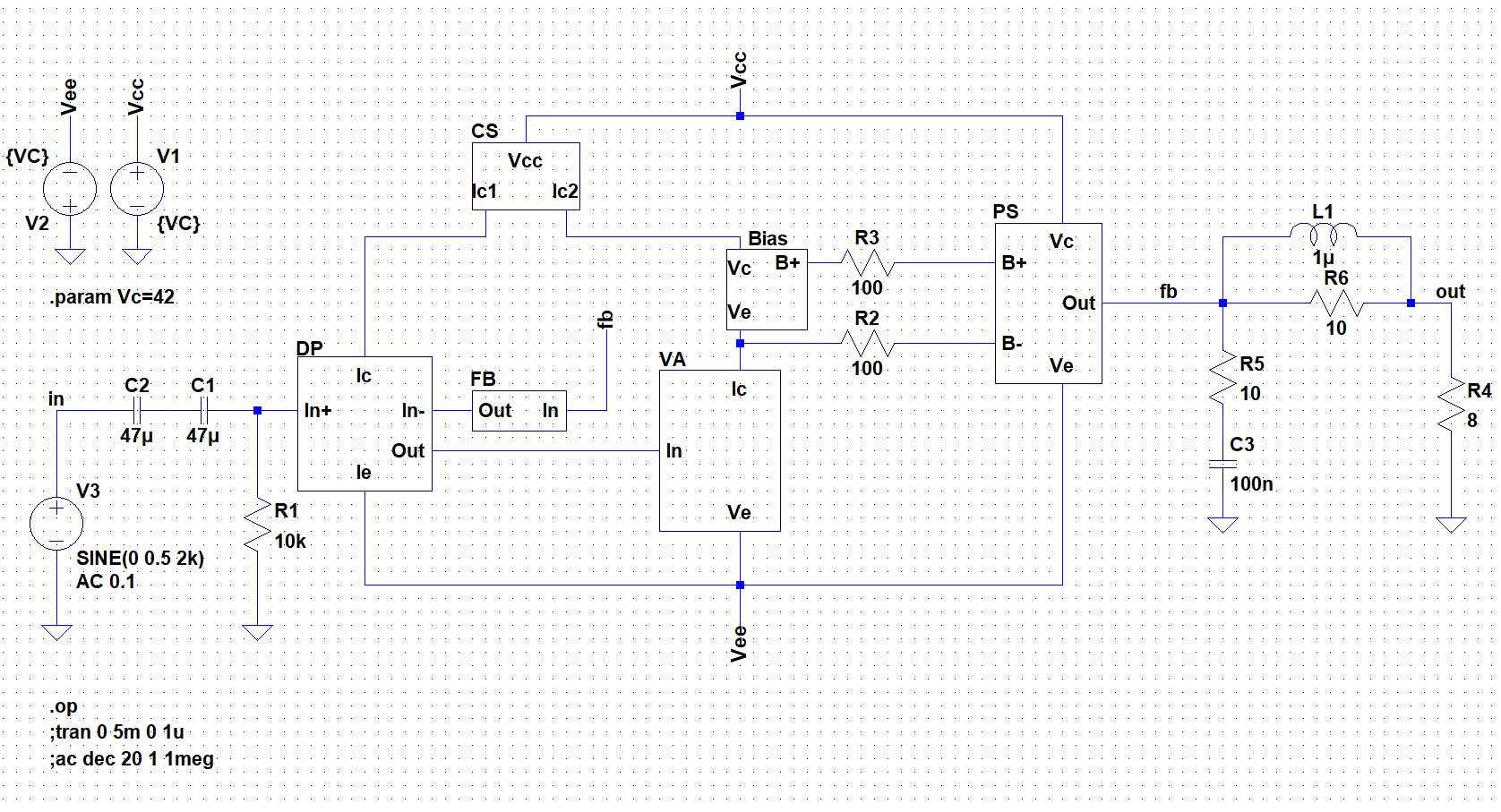
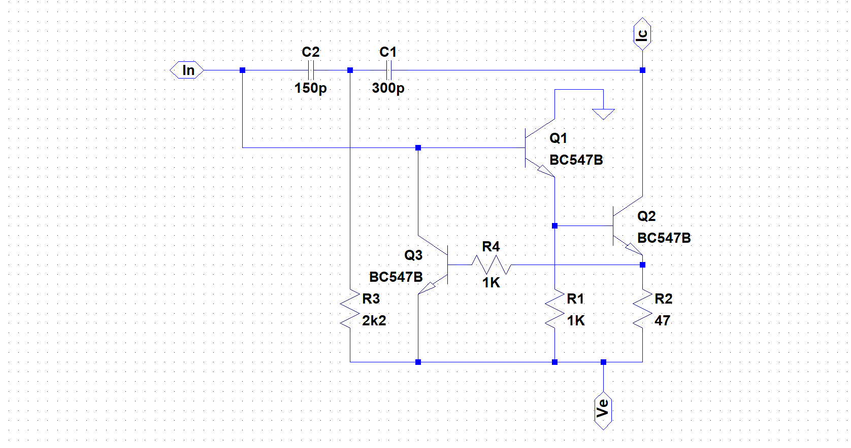
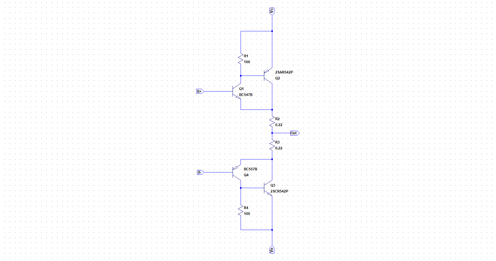
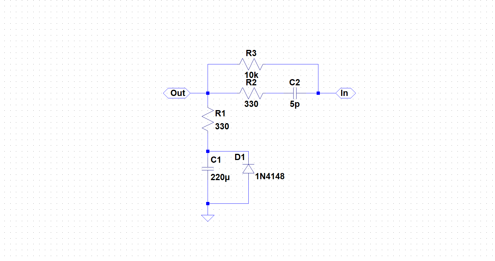
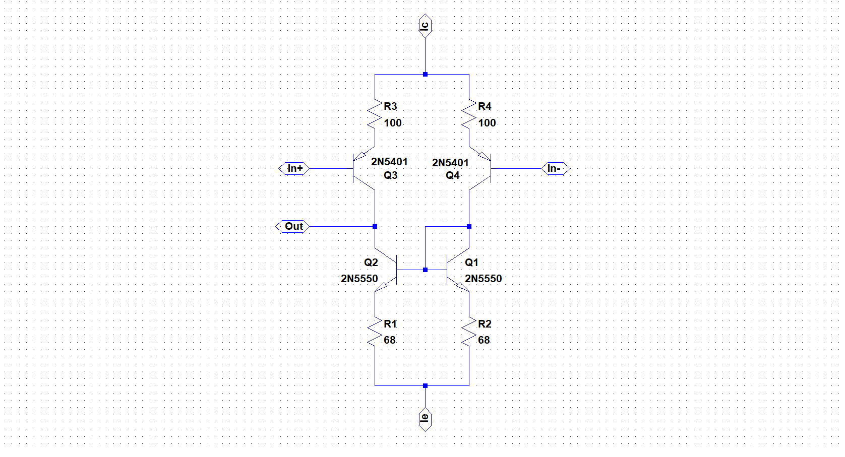
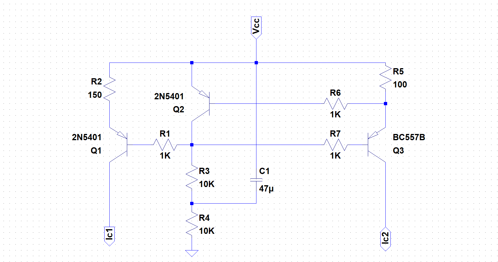
I used LTSpice to examine inner workings of the circuit. I've made a block diagram of every main part of the circuit to simplify the schematics. There you can see an input diff pair stage, voltage gain stage, a current source that feeds them both, output power stage and a bias for the output power stage. I've even put a passive feedback network into the separate block.
---------- more ----------
If you click on a block of every component, you'll find a corresponding schematic. I've used some ready made components available in the LT Spice library such as BC547 and BC557 bjts, instead of creating my own exotic components
I've omitted the current protection circuitry from the power stage due to the simplicity.
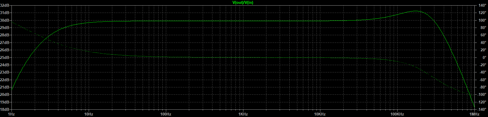
Simulation verified functionality of the amplifier. For a 2kHz sine input I got a clean sine output with a 30 dB gain. FFT diagram showed more than a 80dB attenuation of the 3rd harmonic. AC simulation showed a flat 30 dB gain over whole audio band.
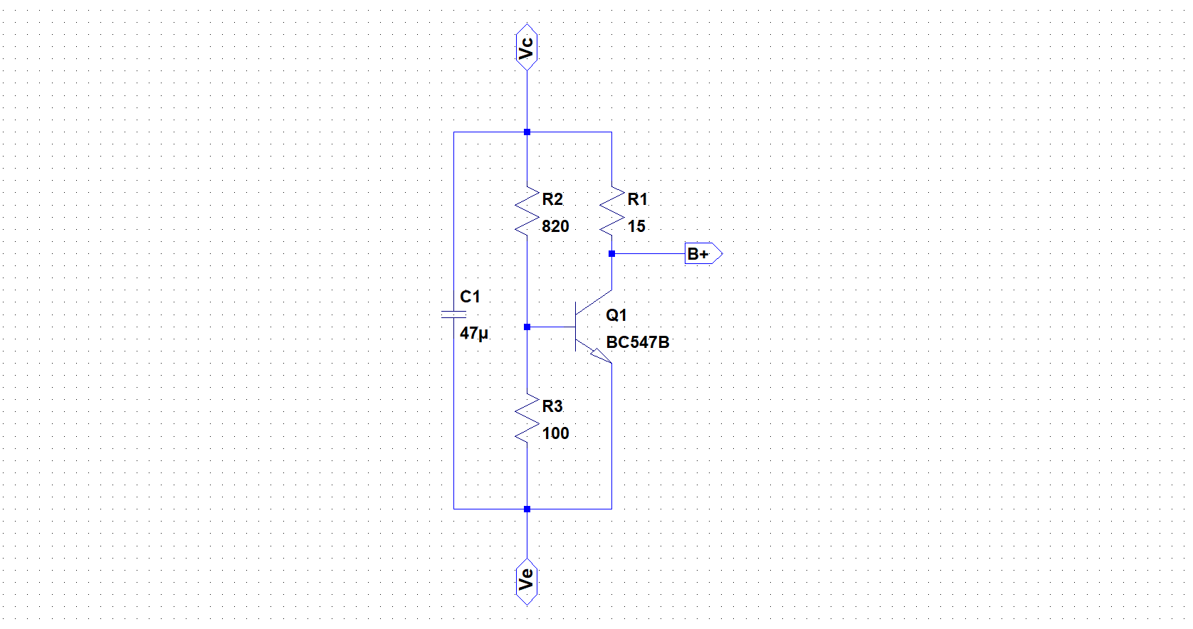
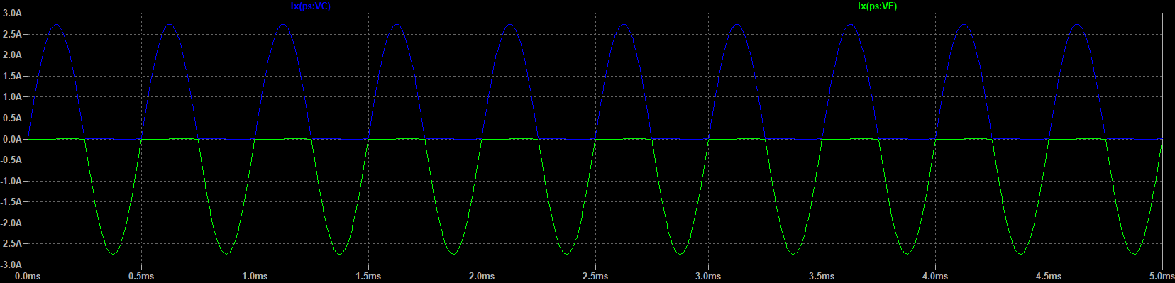
One hugely important parameter that needs to be verified by the simulation is the bias voltage at the output stage. If the bias is too small the PS will fall into the crossover distortion as the output BJTs will cut off the current for too small voltages. If it is too high, the huge quiescent current will flow through the BJTs and eventually cause heating and/or destruction.
 Pero
Pero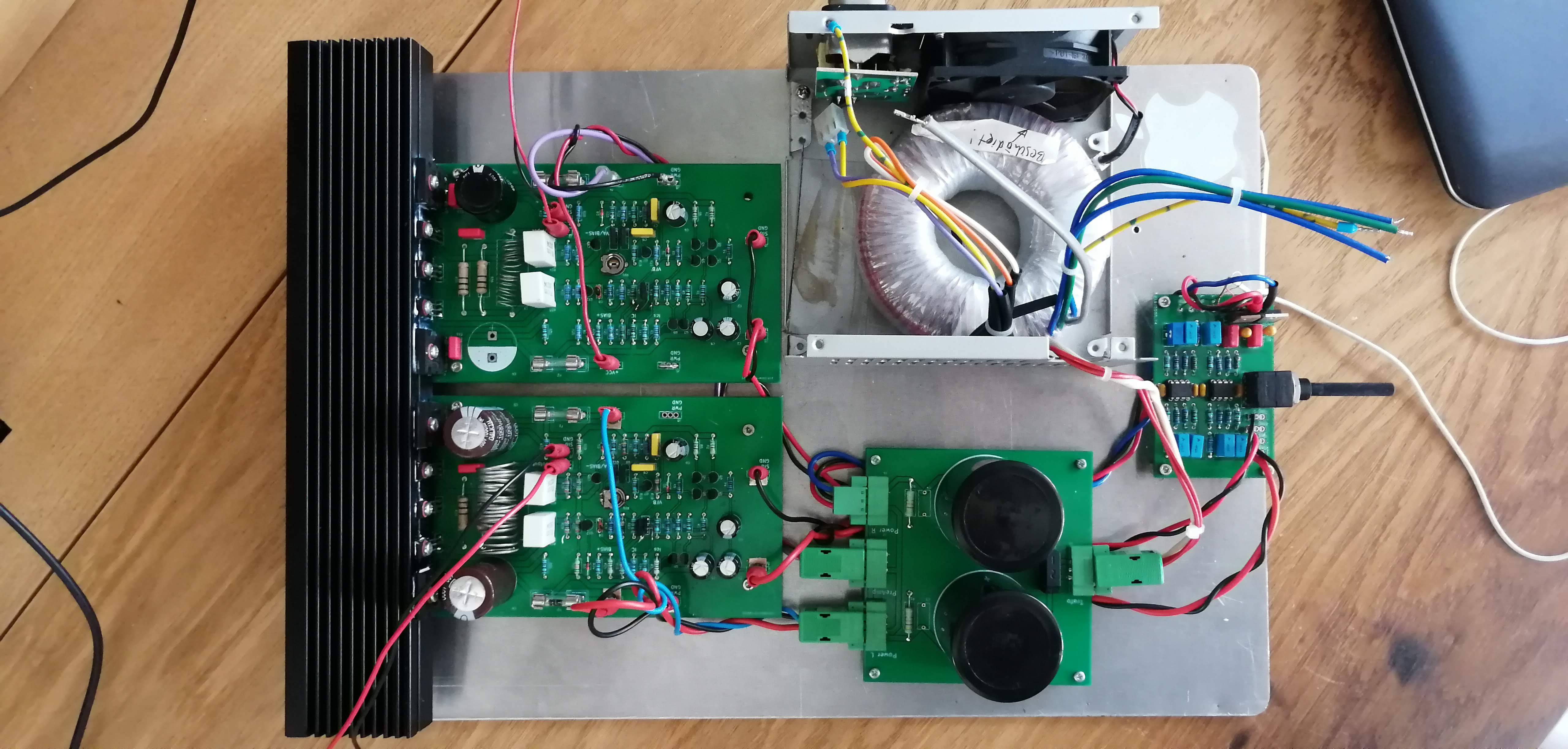 I found a scrap heatsink at the company's dumpster, does the job fairly good.
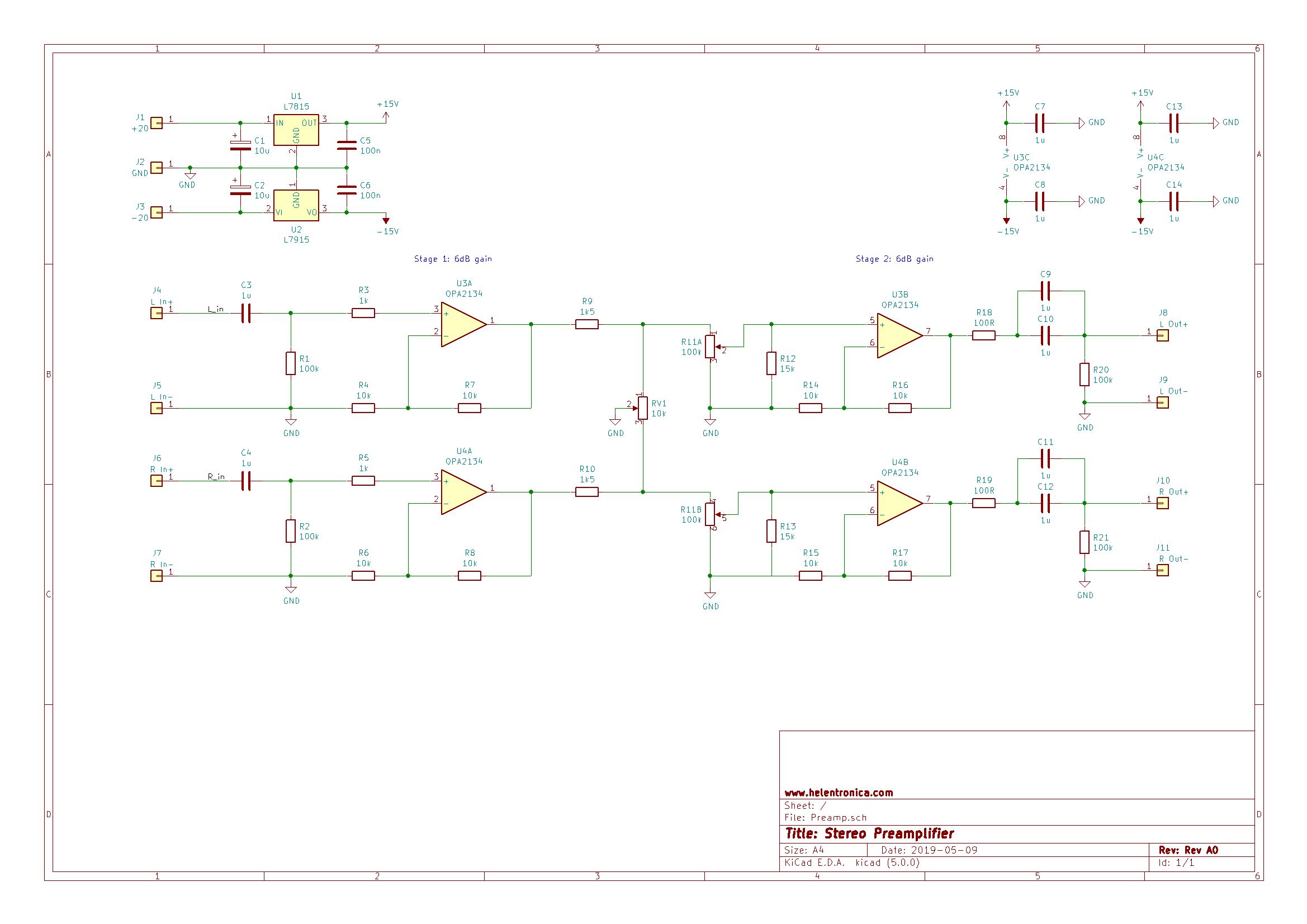
 Zoom in on HF glitch:
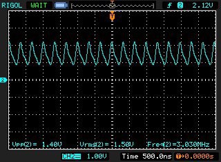

 Beautiful sine wave. I also took a look at FFT, since Rigol scope is powerful enough to crunch the numbers.