So, for the multiplexed clock, I need an anode voltage of 190V.
However, the DC-DC converter board I have is fixed voltage, 170V. ( from https://www.ebay.co.uk/itm/DC-5V-12V-170V-DC-High-Voltage-NIXIE-Power-Supply-Module-PSU-NIXIE-TUBE-ERA-/332647890313)
I wonder how fixed it really is....
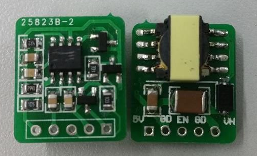
Close-up, front and back, it looks like this:

Note that somebody has kindly ground off the part number etc from the main IC, so we have no idea what it is (presumably to make it harder for people to duplicate), but it also makes it hard for us to work out how to adjust it.
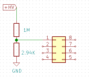
Most DC-DC converters use an arrangement a bit like this to set/maintain the voltage:

Where the output voltage is split via a potential divider and fed back into the chip, so it can adjust/stabilise it.
So, we need to find something on our schematic that looks a bit like that kind of layout.

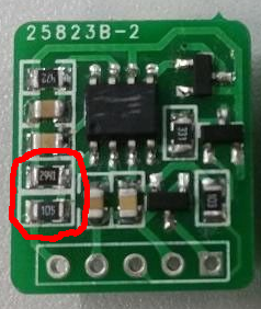
Those two resistors (circled) form a potential divider which is stretched across the HV output, to ground, and the middle of them is connected to Pin 1 of the mystery IC.
So, I decided to try experimenting with changing the value of the 2.94k resistor (labelled 2941), as I suspected it set the HV output.
That gave me the following outputs:
- Resistor value: 2.94k - 170V output
- Resistor value: 2.36k : 215V output
- Resistor value: 2.59K: 197V output
- Resistor value: 2.65K: 192V output
From those, I selected 2.67KOhm as the new resistor value as it's a standard value.
This will give me 192V which is close enough to the 192V I need for multiplexing according to the datasheet, and below the 'absolute maximum' rating of 200V of the tubes.
Of course, I don't actually know the ratings of the components within this DC-DC converter, but it seems to still function OK, and not get too warm. I'll have to see what its' longterm longevity is like....!
 David Pye
Discussions
Become a Hackaday.io Member
Create an account to leave a comment. Already have an account? Log In.
There are lots of adjustable ones on the market using a trimpot for control.
Are you sure? yes | no