 matseng
I tried my best to make soft corners on the two power buses that will form the frame around the LED grid, but it was very hard to get the sizes and spacing between the two even enough. So I ended up with just plain square corners bent with pliers .
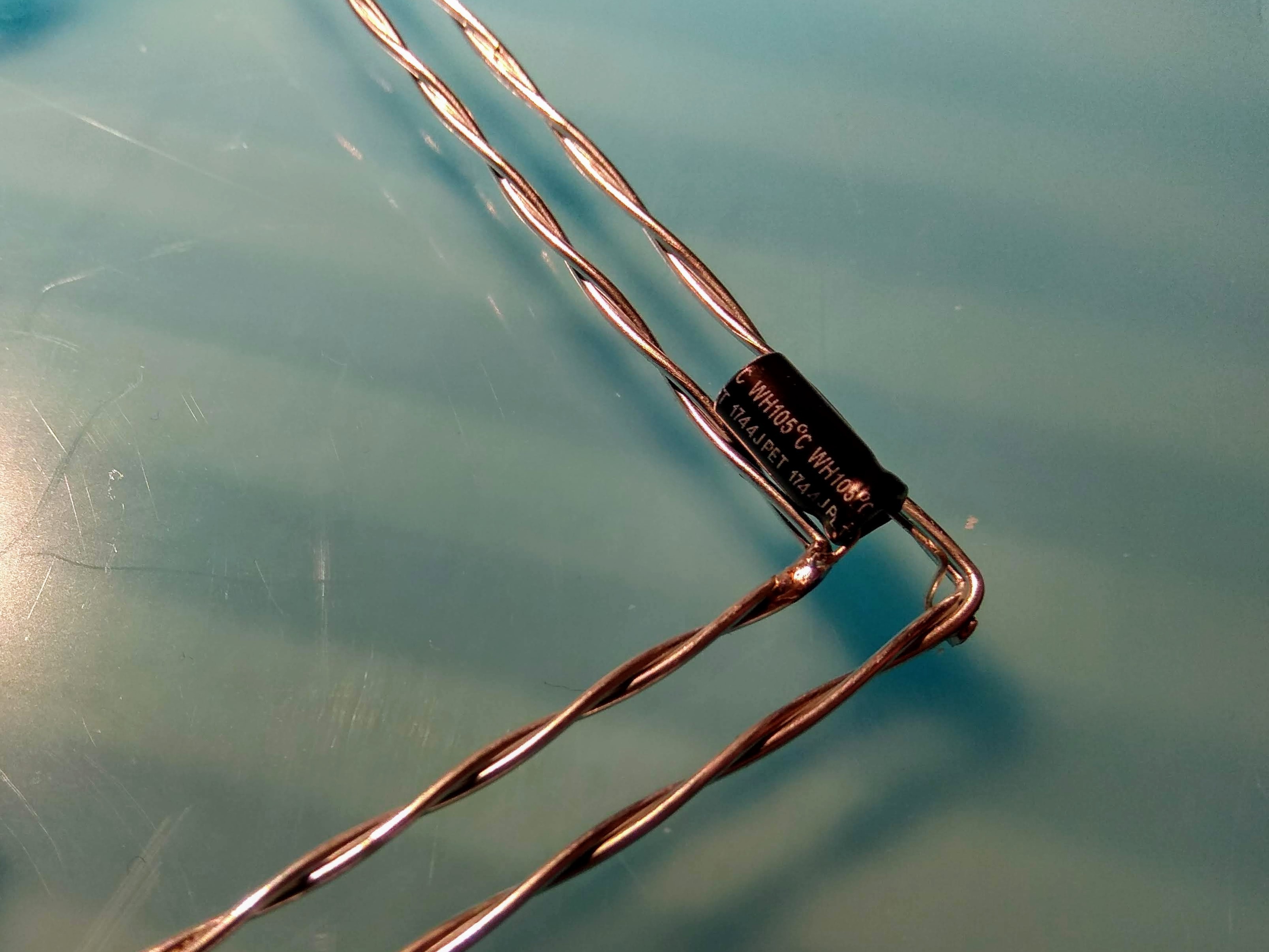
To keep the distance between the two frames I installed a small electrolytic capacitor in each corner.
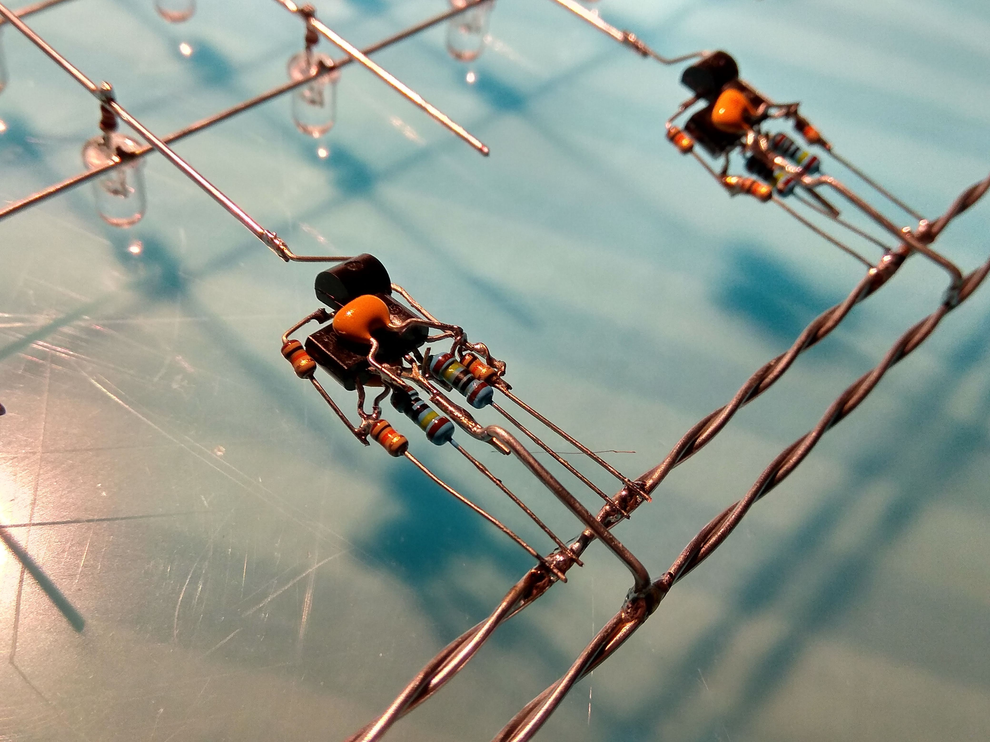
Then I added all the oscillators spreading them out evenly among the top/bottom respective left/right edges.
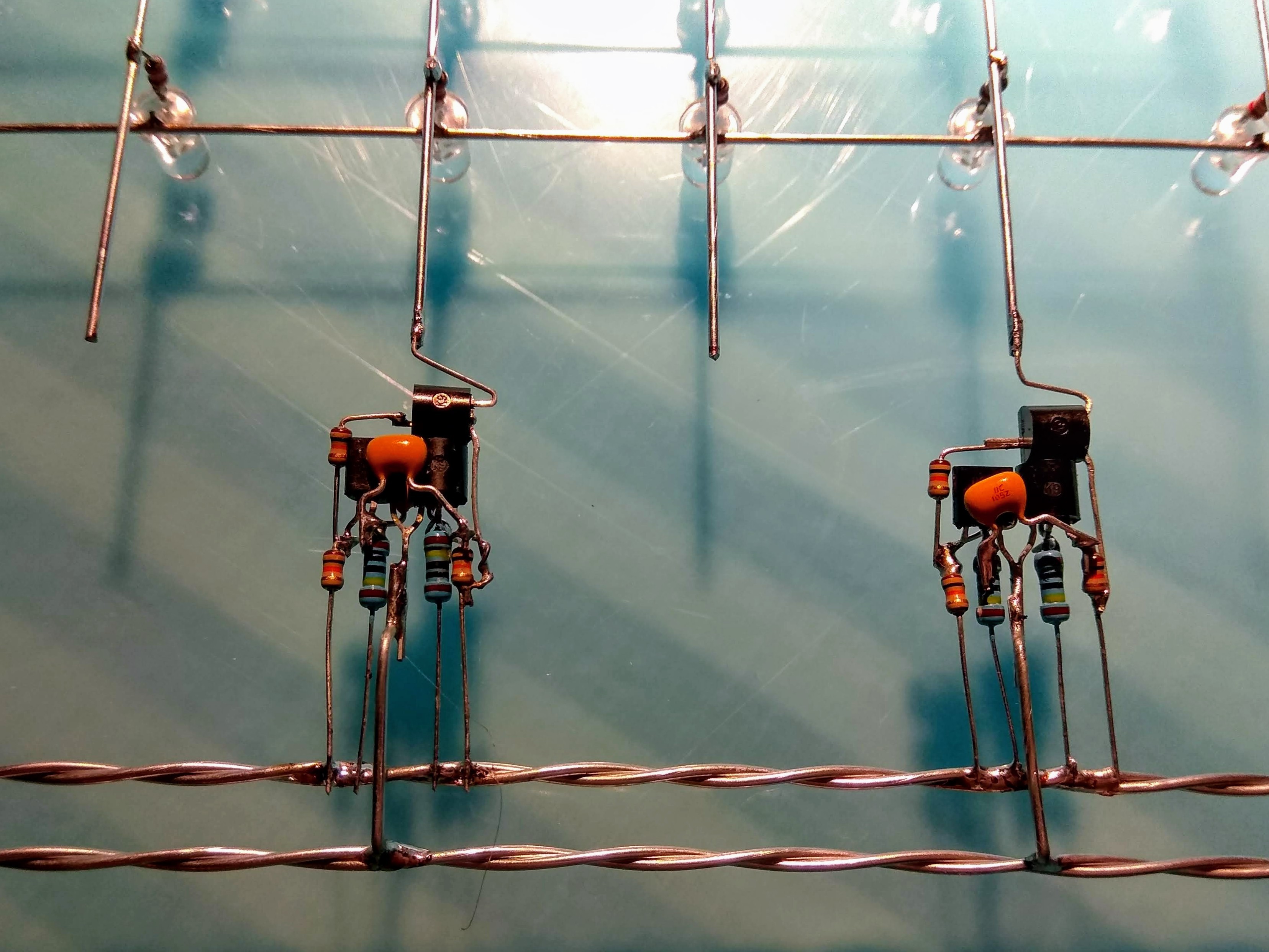
The inner frame is the VCC so all four resistors are connected to it. The outer ground frame is connected to the common emitters of the transistors by a jump-wire that is bent so it doesn't short out the VCC frame.
Discussions
Become a Hackaday.io Member
Create an account to leave a comment. Already have an account? Log In.