 Ákos Melczer
The requirements I set for the PCB design were:
- relatively small size
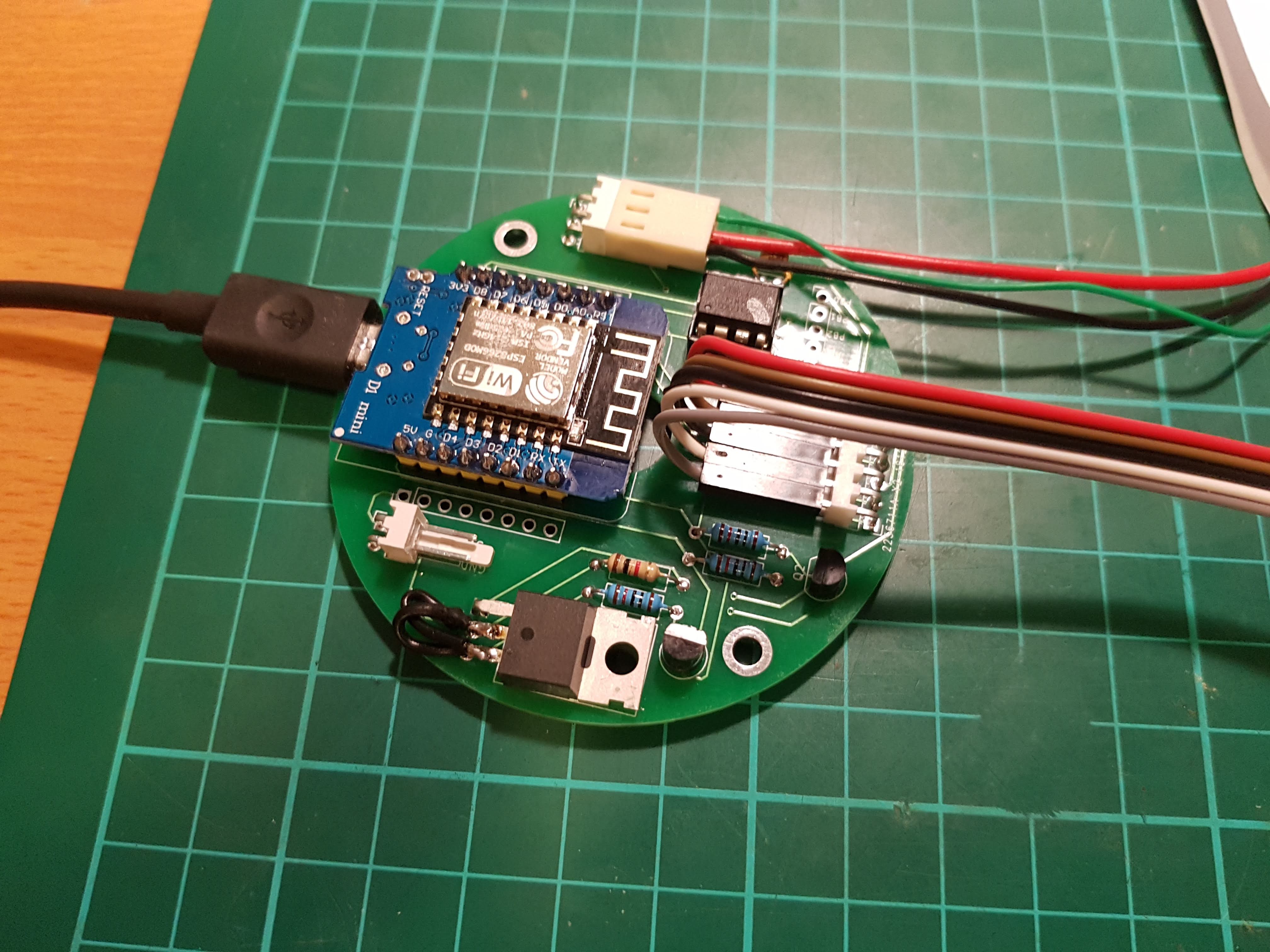
- using THT components for easy soldering and debugging
- circle shape
- connectors for the wires to be able to taken apart
I designed the PCB in KiCAD. Managed to fit all the components on a 70mm circle PCB with a 12mm hole in the middle for wires to run through it. Ordered 10 pieces from JLCPCB and after 2 weeks these showed up.
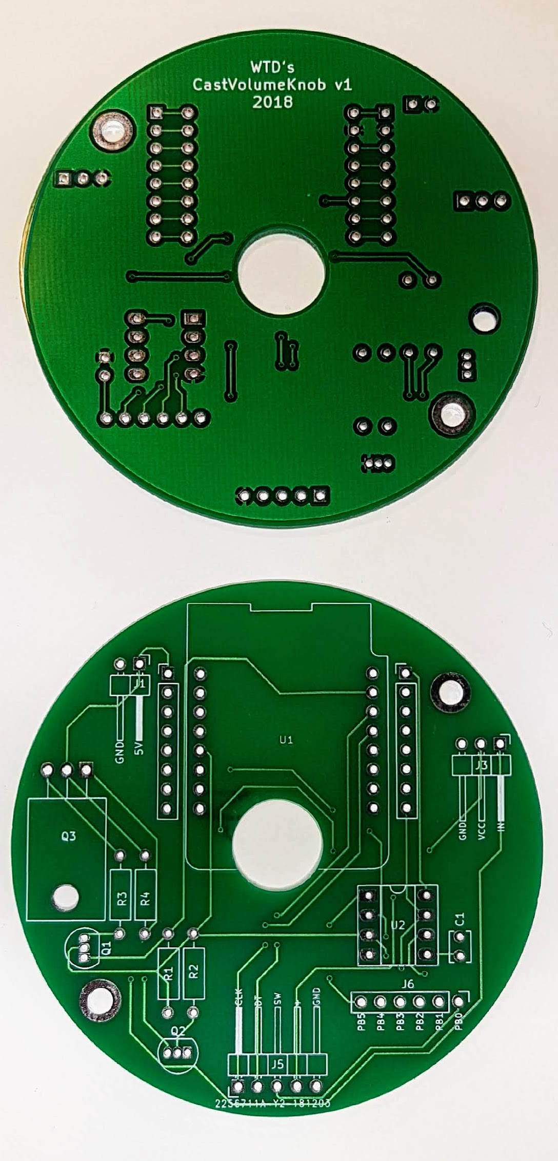
Not counting a minor mistake in my design - MOSFET legs swapped - It turned out great. After soldering on all the components, everything worked as expected.
I designed the case for 3D printing in Solidworks. It consist of 5 parts. Only 2 pieces are needed to be glued together, the other parts connects with screws. The whole model can be easily assembled and disassembled.
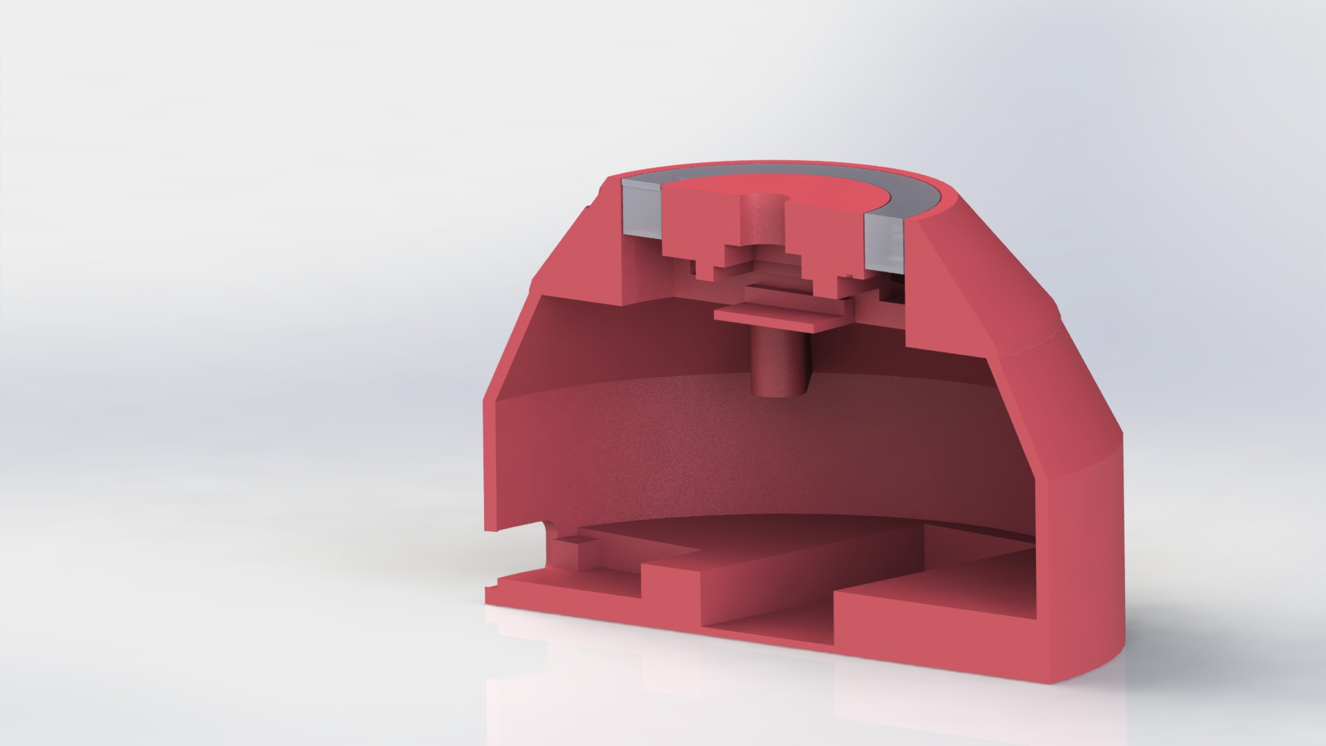
In the top part under the translucent part goes the LED ring. In the top center goes the clickable encoder. in the middle section is the main board. In the bottom is the battery and the charger/boost converter board.
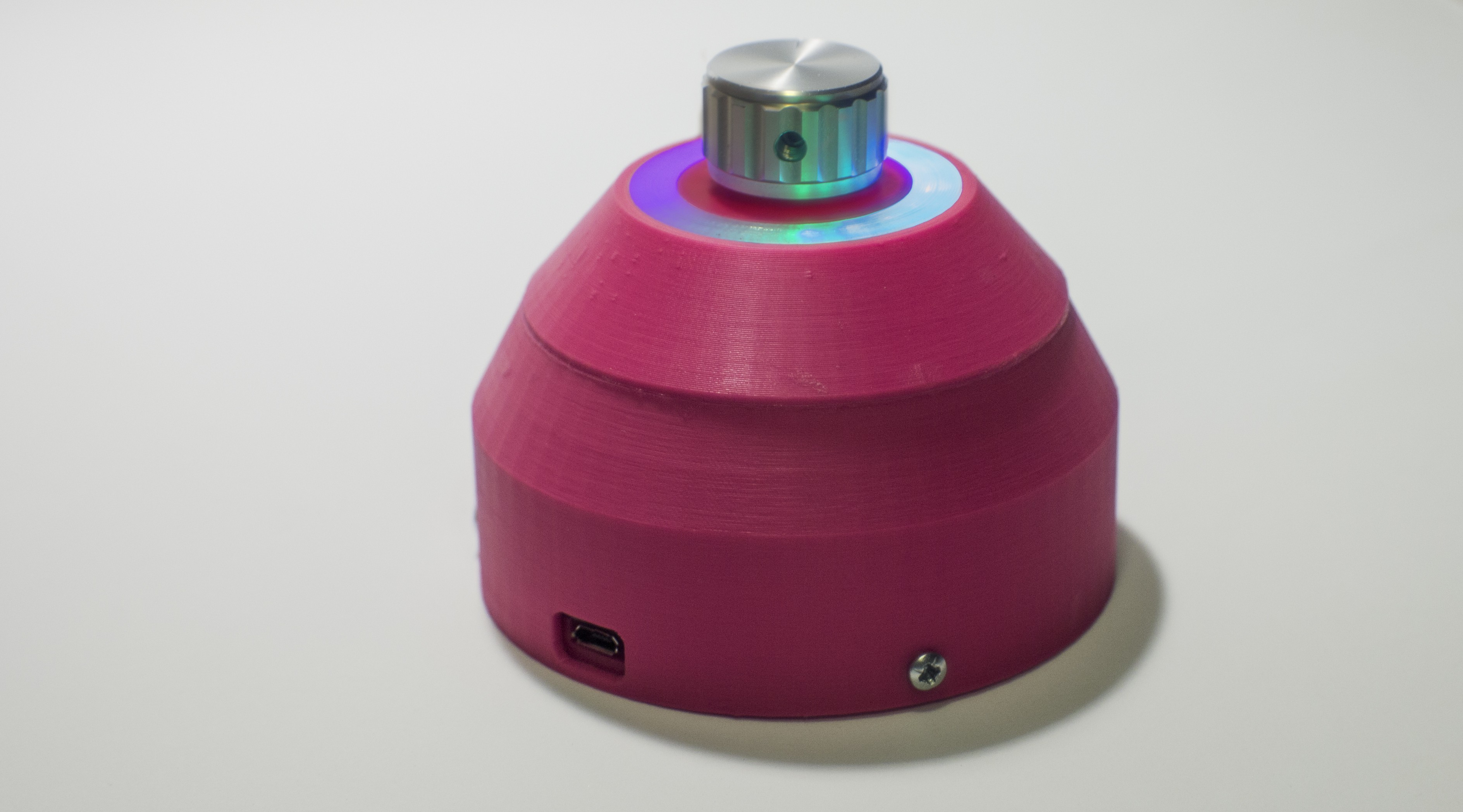
Printed and assembled, working.
Discussions
Become a Hackaday.io Member
Create an account to leave a comment. Already have an account? Log In.