 ziggurat29
Summary
about 2 pm, Monday, January 21, 2019
The Nixie clock has a serial interface, but it's not suitable as-is, and will require some modification.
Deets
As mentioned before, the Nixie clock in this case is a 10-digit model produced by 'Sparkletube'. I got mine years ago on eBay, and the closest I can find currently on the website is this 8-digit model:
https://www.kosbo.com/clocks/in-12-8-digits-nixie-clock-counter.html
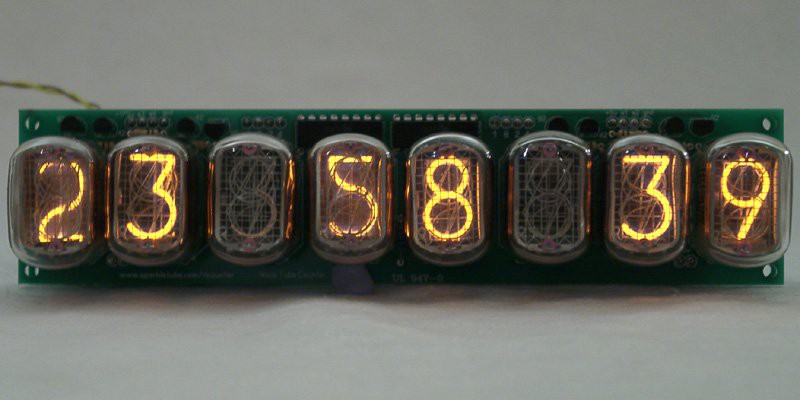
(XXX stock photo image; replace)
The clock works fine, but does have a few quirks that I want to mention for others that may choose to tread this path:
- it uses a MAX771 switching regulator controller to generate the high voltage needed for the nixies. This is a senstive and unforgiving part. You MUST NOT plug in a wall wart that presents more than 15v not even just for a jiffy. I know! I blew mine up immediately with a 12v unregulated wart! And because it's Maxim, you know that means $$$$$$$$$$$$$$$$$$$$$$$, and sometimes also zzzzzzzzzzzzzzzzzz waiting for it to be in-stock. So getcha a 9v switching regulated supply with about 1A load capacity. You don't really need 1A for the clock, but we're going to be strapping on a wifi radio, too.
- the IRF720 is also sensitive. Try to use antistatic procedures when assembling.
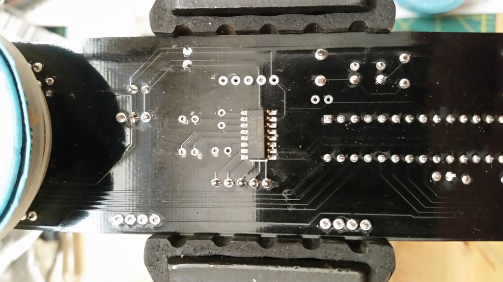
- the board comes with a MAX232 (compatible) for the serial port. While this is unexpected and generally welcome, in this case it's a problem, because the NodeMCU boards are super sensitive and not at all even 5v tolerant. It's not even 5V bemused. You will kill it.
So, pulling off the MAX232 and associated capacitors is the first step.
What's left then is 5V TTL serial. Our only connection to the 5V circuitry is as an input. We output 3.3V logic to a 5V input. So, if I was a sporting person, I would just go for it, because 3.3V logic will still be able to exceed the 5V logic thresholds, but I really hate blowing up boards for one-off projects.
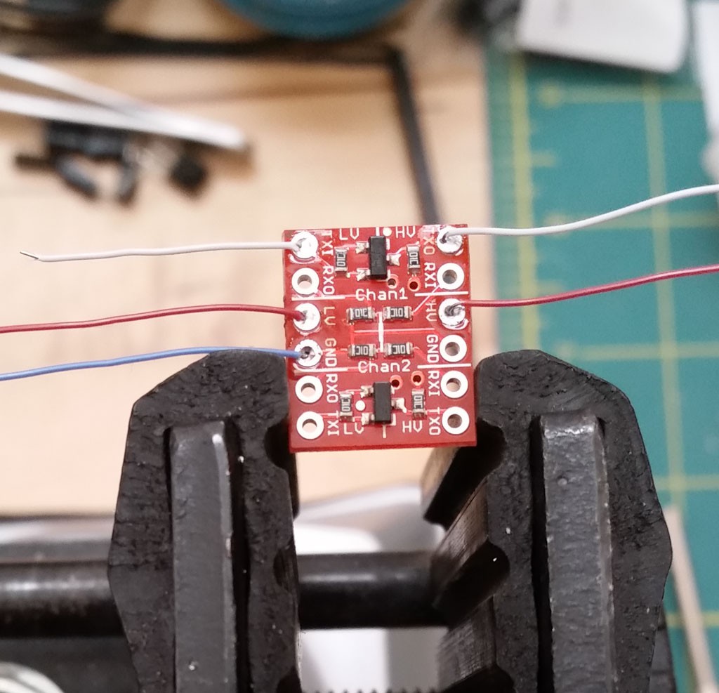
As it turns out, I also have on-hand several level shifter breakout boards. These were some SparkFun boards I got many years back, and are quite discontinued, but alternatives abound.
https://learn.sparkfun.com/tutorials/retired---using-the-logic-level-converter
Short story: it's a MOSFET level shifter. Bidirectional, too, though we don't need that here.
Since I had them on-hand, why not use it to give some more confidence that I wouldn't blow the CPU up? This board has two channels, each with two level shifters, and we just needed one.
But maybe before I get too carried away, I should refamiliarize myself with the NodeMCU board. It's been quite a few years since I last touched it.
Next
Touch the NodeMCU board.
Discussions
Become a Hackaday.io Member
Create an account to leave a comment. Already have an account? Log In.