ziggurat29
-
Nodus Operandi
01/24/2019 at 18:24 • 0 commentsSummary
about 2:45 pm, Monday, January 21, 2019
I refamiliarized myself with the NodeMCU board.
Deets
I had several of these boards on-hand from a prior project, but last I had touched these was years ago, so I needed to refamiliarize myself with the tools, environment, and also circuitry.
It would be redundant to go into too much detail about this popular board, but the highlights for this project seem to be these:
- these boards are a thin hardware wrapper (only slightly more than a 'breakout board') around an ESP12E module, which itself is a fairly thin wrapper around an ESP8266.
- the ESP8266 is pretty awesome for the price, but it is very unforgiving of over-voltages on the I/O.
- as breakout boards are, the support hardware (regulators, etc), are often not quite as robust as you might like for some application. But hey that's why they are so cheap!
- the gist is that you flash a semi-custom firmware that provides a specialized eLua runtime. Ostensibly you do this once.
- the specialize eLua runtime operates in a single-threaded event-driven model reminiscent of NodeJS (hence NodeMCU).
- it's open hardware, so there are many variants on the market. In general, though, the main serial port is used for interacting with the board for all things -- flashing firmware and the interactive Lua REPL. Many boards include a serial-to-USB bridge on-board, and others do not (requiring you to provide that, but they are even cheaper that way).
Creating Firmware
Because the ESP8266 has limited storage space for code, it is not possible to include the entire catalog of available modules in a build that will fit on the device. Instead, you are expected to let the needs of your project dictate what modules you actually will need, and do a special build including just those modules, plus maybe a couple others you speculatively think you might need later.
This can all be done with toolchains and whatnot as per usual with embedded development, but the NodeMCU project has something a bit special: a web based client to a cloud based build system. So, unless you are developing a module to be included in the build, you really don't need to deploy the toolchain at all. (Oh, and they have docker images of the toolchain if you're into that, but I've never tried.) Instead, you check the modules you want, and provide an email for notification, and then a build is kicked off. It takes a couple minutes, then you get an email with links to download the image. They swear they do not use the email for anything nefarious -- you certainly do not have to 'register' with the site. I hope they purge the email from the records after the notification is sent. I certainly have not received any marketing spam in the past 3 years from them.
Your notification will include two links: an 'integer' build, and a 'float' build. Lua natively is float only (well, the version of Lua they are using), but this embedded version includes mods such that you can make an integer-only version if you want. This is useful for embedded projects, but I don't recommend it in this case unless you have demonstrable need.
Flashing a Firmware Image
Once you have the image, you need to burn it into the board. The native way of getting the board into bootloader mode involves a three-fingered salute of holding a gpio line a certain way with reset asserted while powering on and releasing a certain way. Then the bootloader becomes active and it works over the main serial port. Some other boards (such as mine) made clever use of the RTS and DTR line of the USB-to-serial bridge chip, and you do not have to mess with any of that rigmarole given a cognizant flashing application.
Before I go much further into some tools, I should point out that the normative place for this information is:
https://nodemcu.readthedocs.io/en/master/
The following discussion is my journey through using these tools, but it is not the only journey possible.
The flashing application I use is the ancient native one ('ESP8266Flasher.exe') that works only on Windows. I use it because I am running on Windows, and I don't have to install anything. It is old, however, and and it is a bit fiddly. The way the NodeMCU team more heartily recommends is to use the 'esptool', which is a Python application. So you will first need to install Python. And you will need to install the 2.x version of Python, because 3.x is straight out (this is apparently common in the Python world, but I'm not so hip to that jive). It is a command line application. I have used it -- it works -- and very occasionally I will reach for it if I want to do something explicit like 'erase the flash' or 'dump the flash' or 'etc'. But you need to know the incantation. E.g. for me, to flash, goes something like this:
python esptool.py --port COM3 write_flash -fm dio 0x00000 ..\nodemcu-master-16-modules-2019-01-21-23-30-40-float.bin
python esptool.py --port COM3 write_flash -fm dio 0x00000 ..\nodemcu-master-16-modules-2019-01-21-23-30-40-float.bin
Once you have flashed the NodeMCU firmware onto the board, then your board should come up into a Lua repl. It is hard-coded to look for an object named 'init.lua' which is effectively your 'autoexec.bat'. Your freshly-flashed board will not have this object, so it will just be sitting at the interactive Lua prompt.
Feel free to connect to the board at 115200 N81, and behold the wonder of it all. Here are a couple things you can do right away:
print ( "Hello, world!" )
= node.heap()
node.restart()
Whee! But seriously, this can be quite handy for little interactive tests. For the rest, there are files of Lua code.
The 'files' on the NodeMCU board are actually in a SPIFFS partition of the serial flash memory that is certainly included on your board. Actually, it is included in the ESP12 module, under the RF shielding can, along with the ESP8266 chip. Almost certainly you board will have a 4MB flash chip.
'Source Files'
How do you get the files onto the chip? Well, there are other tools. The one I'm using is 'ESPlorer', which is a Java application. So there is another runtime environment you'll need to install if you want to use it. I thought that surely the copy I had from 3 years back would be out-of-date, but no, it's the current version. The application seems to have been intended to be more of an IDE, but it does fall a bit short of what one might expect in that arena. I just use it to transfer files to the board.
I found that you have to diddle with it a bit to get it to work -- at least with the NodeMCU boards that are derived from the reference design from the NodeMCU team. You need to set some things:
- on the left side, on the 'NodeMCU & MicroPython' tab, there is another tab 'Settings'.
- Ensure the 'SerialPort' 'Autodetect firmware' is off
- Ensure the 'Send' 'Turbo Mode' is on
- Ensure the 'Send' 'Dumb Mode' is off
- On the right side is a choice for COM port; select the correct one. Set the bit rate to 115200.
Once you have done that, the following buttons will be used frequently:
- 'Open'
To open the serial port to connect to the board. - 'Heap'
For some reason the application tries to do some auto-recognition, and will fail, and give you the visual appearance that it is not connected. The 'Heap' button will send a canned command (to get the amount of free heap available). We don't really care about the response, but the fact that a response comes back at all seems to make the application happy, and thus unlock all the other UI elements. - Upload
To get your files onto the spiffs partition - 'Reload'
To list the SPIFFS partition, so you can delete files (or copy them back to your computer, if you need)
Once you have got your sea legs with these tools, you'll be ready to start to do real work.
Real Work
Real work consists broadly of two things:
- writing Lua code
you'll need to know Lua for this. Fortunately, Lua is 'easy'; it was intended to be used by non-programmers. It does have many quirks, though. Like 1-relative arrays, and ~= for not equals, and 'it's global unless you explicitly say local', and a bunch of other things. Also, you need to be aware that this environment is based on Lua 5.1, which is a bit old. This affects how much trust you should give at first face to information you get from the web, which could be for 5.2 or 5.3. To me, Lua feels a bit like Javascript, but without curly braces, and a lot of ugly Javascript quirks. - writing for the NodeMCU execution environment
the runtime environment is single-threaded event-driven like NodeJS. I found this jarring when I first did some NodeJS (and still do, for the most part), and it can be just as jarring in NodeMCU if you're used to synchronous execution. However, in the big picture, I think it's possibly worth it. If nothing else, the fact that there are existing modules for high-level things like http servers definitely behooves one to get competent with it.
Back to Hardware
But for now, I need to get the hardware working a little bit more. I need a serial port, and then of course there has to be power.
There are two serial ports on the ESP8266. One is a 'full' serial port ('uart0'), and the other is a 'half' (TX only) serial port ('uart1'). The 'full' serial port is typically hard wired to a USB-to-serial bridge chip (either a CH340 or a CP2102), so is not quite so easily available for use with your application. The 'half' serial port is TX-only, so for most applications requiring a serial port you will not be quite so happy. Two things, though: 1) you can reassign the uart0 to alternate pins, and 2) this application doesn't need RX. So we're golden using the oft reviled uart1 in this application. But if you did need a full serial port, you would choose to redirect your pins to the ones on the boards headers. This then also makes the board inaccessible from the USB serial, which complicates other activities, but that's what you gotta do! Fortunately here we don't!
We don't have any other peripherals, so we can stop contemplating the others, except for maybe the button and the led if we want to use them for special purposes. None come to mind yet.
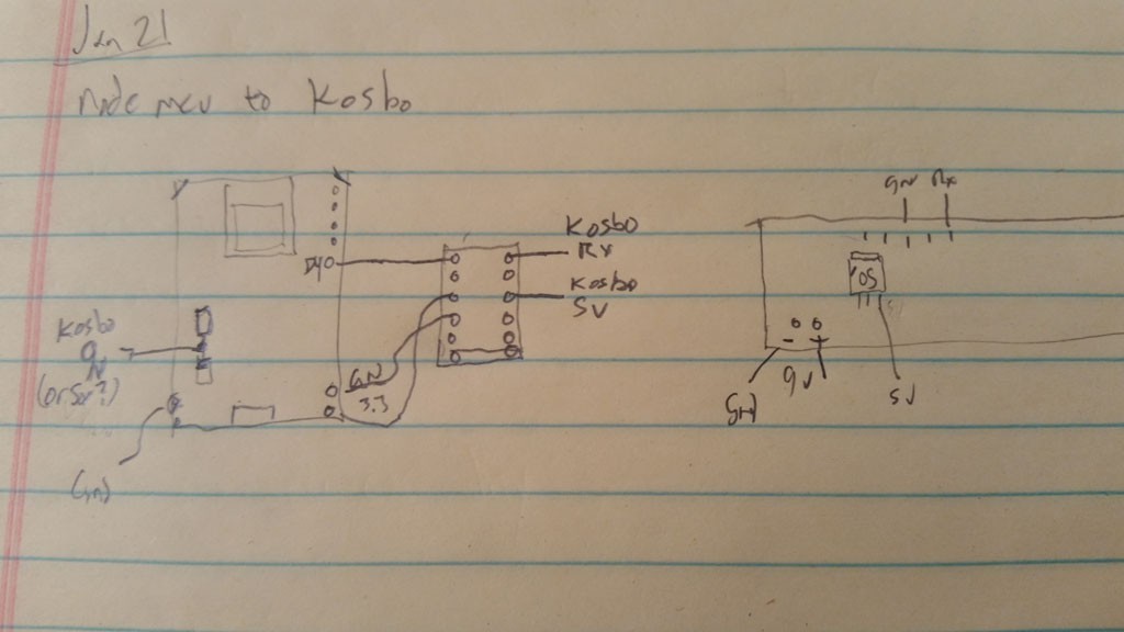
For power, it's best to look at the schematic. This board (as with many) are intended to be powered from the USB port -- either by connection to computer, or just by connection to a USB charger. That's OK, but we are going to want to power from the Nixie clock source. Actually, we would like to power from both sources, and for it to be safe to have the clock powered on, while the USB is also plugged into the computer. This means steering diodes, and often times boards like this lack such. You need to look at the schematic.
On this particular board, we do at least have a diode between the USB power and the 3.3v regulator. Thank you. (The same cannot be said for the Blue Pill, alas.) However, for some reason the designers brought the USB side of the power out to the header, but not the regulator side (i.e. on the other side of the diode). This is not good for us, because if we were to put the Nixie power on the USB power, Mr. Computer will cry. And then you will cry. So it will be necessary to tap off of a component on the board. The diode itself is rather large in this case, so that is my choice.
My electrical plan is roughly this:
![]()
So it's time to get back to melting lead.
Next
Crufting it together.
-
You're Not Just Whistling Nixie
01/23/2019 at 17:43 • 0 commentsSummary
about 2 pm, Monday, January 21, 2019
The Nixie clock has a serial interface, but it's not suitable as-is, and will require some modification.
Deets
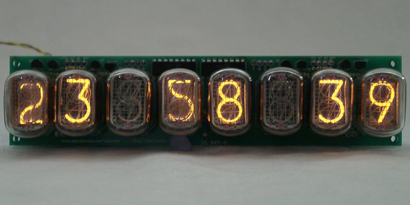
As mentioned before, the Nixie clock in this case is a 10-digit model produced by 'Sparkletube'. I got mine years ago on eBay, and the closest I can find currently on the website is this 8-digit model:
https://www.kosbo.com/clocks/in-12-8-digits-nixie-clock-counter.html
![]()
(XXX stock photo image; replace)
The clock works fine, but does have a few quirks that I want to mention for others that may choose to tread this path:
- it uses a MAX771 switching regulator controller to generate the high voltage needed for the nixies. This is a senstive and unforgiving part. You MUST NOT plug in a wall wart that presents more than 15v not even just for a jiffy. I know! I blew mine up immediately with a 12v unregulated wart! And because it's Maxim, you know that means $$$$$$$$$$$$$$$$$$$$$$$, and sometimes also zzzzzzzzzzzzzzzzzz waiting for it to be in-stock. So getcha a 9v switching regulated supply with about 1A load capacity. You don't really need 1A for the clock, but we're going to be strapping on a wifi radio, too.
- the IRF720 is also sensitive. Try to use antistatic procedures when assembling.
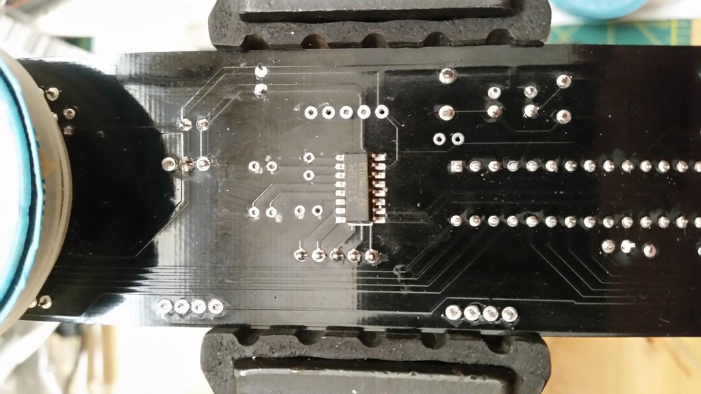
- the board comes with a MAX232 (compatible) for the serial port. While this is unexpected and generally welcome, in this case it's a problem, because the NodeMCU boards are super sensitive and not at all even 5v tolerant. It's not even 5V bemused. You will kill it.
So, pulling off the MAX232 and associated capacitors is the first step.
![]()
What's left then is 5V TTL serial. Our only connection to the 5V circuitry is as an input. We output 3.3V logic to a 5V input. So, if I was a sporting person, I would just go for it, because 3.3V logic will still be able to exceed the 5V logic thresholds, but I really hate blowing up boards for one-off projects.
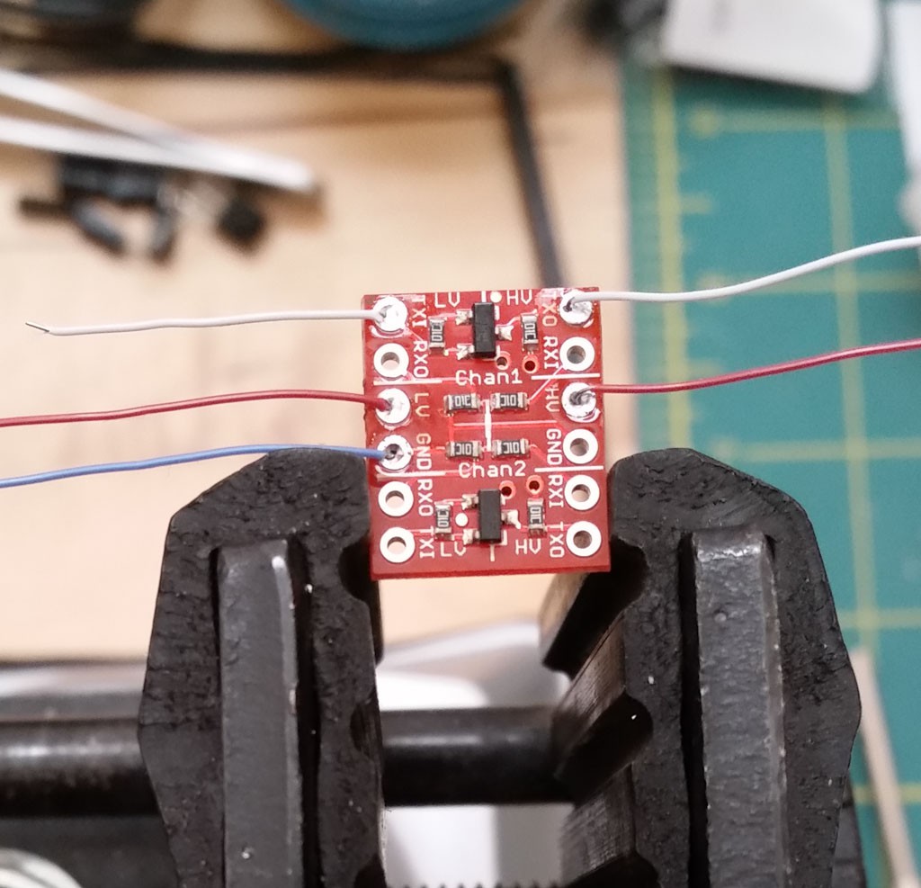
As it turns out, I also have on-hand several level shifter breakout boards. These were some SparkFun boards I got many years back, and are quite discontinued, but alternatives abound.
https://learn.sparkfun.com/tutorials/retired---using-the-logic-level-converter
Short story: it's a MOSFET level shifter. Bidirectional, too, though we don't need that here.
Since I had them on-hand, why not use it to give some more confidence that I wouldn't blow the CPU up? This board has two channels, each with two level shifters, and we just needed one.
![]()
But maybe before I get too carried away, I should refamiliarize myself with the NodeMCU board. It's been quite a few years since I last touched it.
Next
Touch the NodeMCU board.
-
Internet of Nixie Clocks - The Feeling Begins
01/23/2019 at 02:58 • 0 commentsSummary
about 1 pm, Monday, January 21, 2019
Today is a minor holiday where I am, so that means I have a new opportunity to shirk more productive activities and instead pursue frivolous ones.
For today's mini-project, I am going to realize something no-one needs: an Internet-enabled Nixie Tube Clock. Or more accurately, I am going to Internet-enable an existing clock that has a serial port and accepts commands.
Deets
Earlier today, I was reviewing some of my old web site accounts and I noticed one for ThingVerse that I had not touched in several years. It was used for a demo I did for a friend who was wanting to make a data logger. It just took a reading from a DHT22 and posted it to ThingVerse. It was implemented with a NodeMCU board (and since it's been posting the temperature and humidity in the lab for the past 3 years, I guess it is reasonably robust!) This made me think of another thing....
I have a few Nixie clocks, and one is a bit interesting in that it is just a bar of IN-12s -- no spacing of the digits or little NE-2s to punctuate the digits. Instead, it is a 10-digit bar, and non-lit digits provide the spacing. Additionally, this clock can be sent digit sequences over a serial port which will cause those digits to be displayed literally, instead of the usual clock display. Why? Who knows. A 'like' counter for youtube? Or a twitter? Your kickstarter raise? Who knows -- you just have to supply the digits.
This particular clock in this case is one made by 'Sparkletube', who runs https://www.kosbo.com. I'm sure it is a labor of love for M(r|s). Sparkletube, and stock is catch-as-catch-can. Mine is a 10-digit unit, but there are also 8-digit ones as well.
I have a kind of 'art nook' in a high place on a wall in my living room where I thought I could put it. The IN-12 digits are not as big and sexy as the unobtanium IN-18, but it should still be quite readable across the room. Of course you'll never be able to get to the buttons up there, and these things tend to keep rather poor time as it is, so it will be even less fun than the normal running around the house when we change to summer time and back.
My original intention was to use some stray board and facilitate Ethernet via an ENC28J60 or something, but that was going to be more than a day project, and hence why I never put forth the effort. So it has been sitting in a box in my lab for years, yearning for the day that it will be loved and on display for all.
So why not use one of the NodeMCU boards? Because they were so cheap, I had bought 5, so I had plenty extras on-hand. So, in theory, just add some wire, solder, and code, and then maybe I will have the Nixie clock on my local network? And by gateway, the World?!
Let's see if I can do it as a one-day project, before I have to go back to gainful employment....
Next
Getting familiar with the Nixie clock.
The Internet of Nixie Clocks
Wherein the tubes of Nix do bridge betwix the worlds of form and ether. I see no reason one should bridge, but that won't stop me, either.