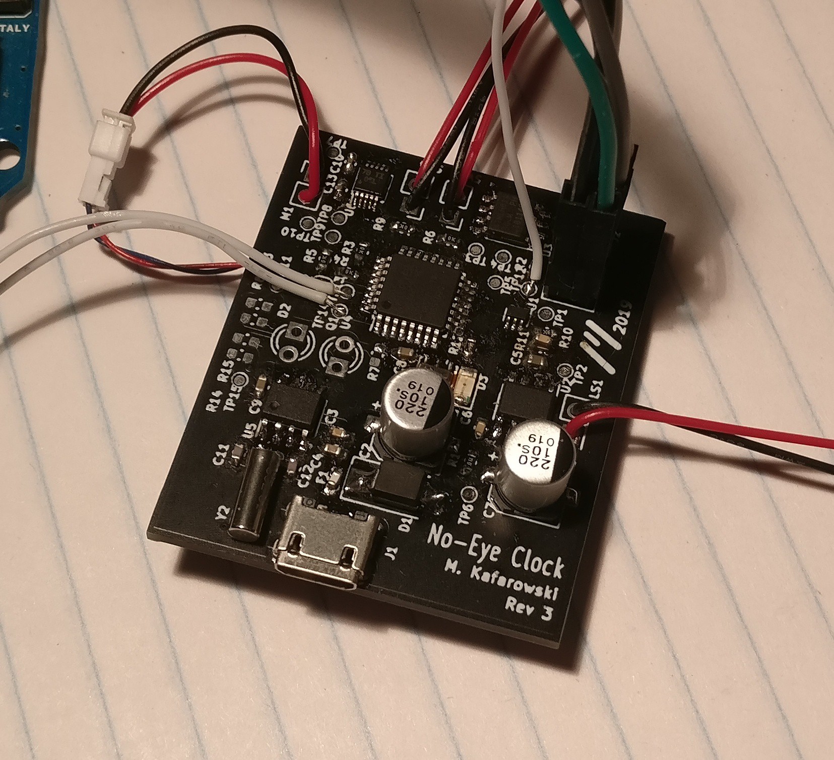
I received the V0.3 PCB a few weeks after my last posting and was eager to assemble it and hear how much better the audio sounded now that I switched from I2C to SPI.

I stayed up late soldering and programming a test program with the “PM” sound that was giving me issues before. After soft-bricking a few ATMega328PBs with incorrect clock source fuse settings, I got them right (it’s -Ulock:w:0x3F:m -Uefuse:w:0xFF:m -Uhfuse:w:0xD9:m -Ulfuse:w:0xCF:m for a 16MHz ceramic resonator), then I downloaded the firmware, plugged in the speaker, and…
It sounded the same. The same distorted, shrill sound that I thought was related to I2C not being fast enough for 8KHz audio on V0.2.
Over the past two days I’ve been troubleshooting the issue, going so far as to breadboard the whole audio circuit to prototype filtering techniques. I considered that the shrill noise may be coming from the the high frequency components generated by the discrete stepping from the DAC. I created a sine wave data pattern so that I could easily analyze it on the scope. After trying numerous hardware solutions, I found that configuring the audio path to go from DAC -> Passive RC (fc = 1000Hz) -> Buffer -> Voltage Divider -> LM386 -> Speaker produced semi decent results, outputting a pretty nice looking sine wave from my discretized input. The audio quality for the “PM” file was indeed better, but was pretty quiet and I could still hear a shrill noise.
Turns out my mistake wasn’t in hardware at all, and that I was only right about I2C being too slow in theory. During troubleshooting I decided to try reexporting the audio files. This is when I discovered that the data I had previously exported wasn’t formatted as unsigned 16-bit words, but instead as unsigned 8-bit bytes. Because my code was expecting a 16-bit sample, in reality it was combining two separate 8 bit samples into one 16-bit word, which was then passed to the DAC. The meaningless combination of these samples caused the distortion. Because my data was already in a 16-bit form, I implemented a workaround that read the word twice, but passed the most significant byte, then the least significant byte separately to the DAC before moving on to the next word. The audio quality improved tremendously, and it sounded good even without all my new fancy filtering!
I dug out my V0.2 board and implemented the fix in software. Although the sound was much clearer on this board as well, now that the audio was essentially playing at double the sample rate (two 8-bit samples needed to play for every original 16-bit sample), the I2C bus couldn’t keep up, and the audio took on a lower pitch than the original file, although the distortion had disappeared.
This ordeal taught me the value in questioning my assumptions. I had already calculated that i2c would be too slow before I assembled V0.2 (but after I had designed it!). With this in mind, the fact that the audio was distorted seemed to make sense. But had I investigated a little bit more into the actual symptoms from basic level, I probably could have improved the audio quality in V0.2.
Next steps:
- Software
- Test IR Triggering
 Michael Kafarowski
Discussions
Become a Hackaday.io Member
Create an account to leave a comment. Already have an account? Log In.