 Paul Kocyla
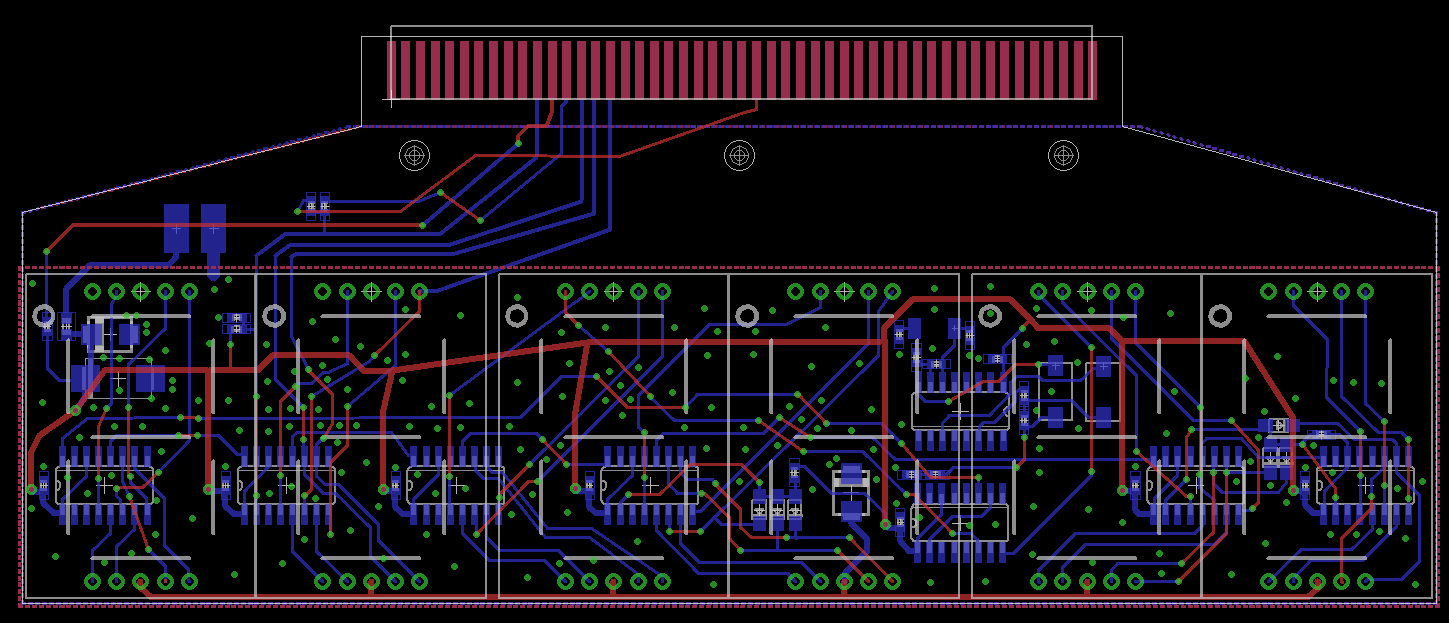
Here´s the PCB layout of the clock with the interface to the LVDC module:
The parts are mounted behind the 1-inch 7-segment displays.
The circuit is based on the schematic by danyk666, it´s a classical counter circuit which uses counters 4060 and 4026. It doesn´t need BCD to 7-segment decoders, as the ICs do the job already. A quick design here, not the most beautiful routing, but will do the job.
Anyway, it´s a quick build.
Discussions
Become a Hackaday.io Member
Create an account to leave a comment. Already have an account? Log In.