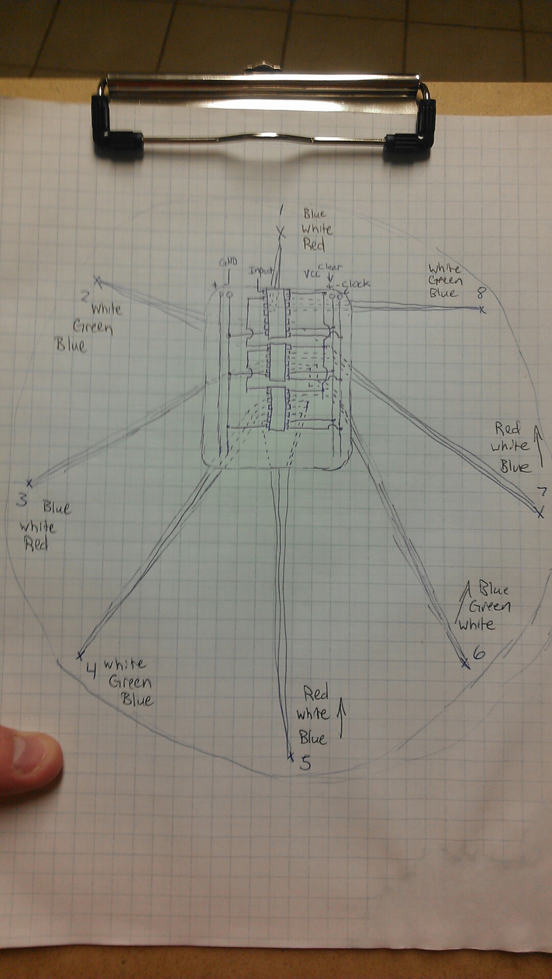
I have had the designs in my head for this for a while, but aside from basic sketches, I haven't drawn it all out. Also while doing this on graph paper with a pen, I realized I need to get some CAD skills for schematics.

The board in the middle houses the shift registers and all the output to the LEDs. The circle is the board (like wood) that it is mounted to from which the lights will hang. I also discovered that I will have to figure something out for the shift registers. If you're not familiar with how a shift register works, please visit Wikipedia as they have an excellent illustrated example. In the demo binary counter, I was only using one shift register; interfacing it with the arduino with three wires to tell it what to output on its eight pins. The code was something like:
int i
shiftout i
i = i + 1 as long as i =< 255
delay 1000
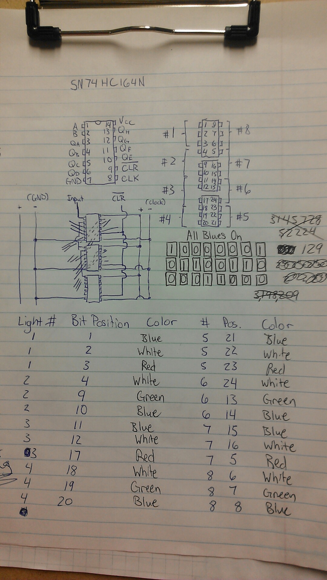
This code generates a 8 bit binary value that is output to the shift register. So for 1, it is 00000001. 2 would be 00000010, and so on. These values are interpreted by the shift register as which of its outputs to turn on or off. The problem lies in my use of multiple shift registers in which lights that are physically sequential are not always addressed sequentially with the binary value that is passed to the shift registers. I worked it out (again on paper):

In the top right is a diagram of the three shift registers if you only care about the outputs and their number and location. The brackets show which light every three outputs runs to. I made a table of every LED color, light fixture number it is in, as well as the bit number required to turn it on. I worked out what the three 8 bit packets would be if I wished to turn on one blue LED in every fixture, that is blocked out in the middle of the page. I mistakenly thought to calculate the 24 bit number in decimal before I realized that I would be sending three separate 8 bit packets instead of one that it wouldn't be possible for an 8 bit micro to handle.
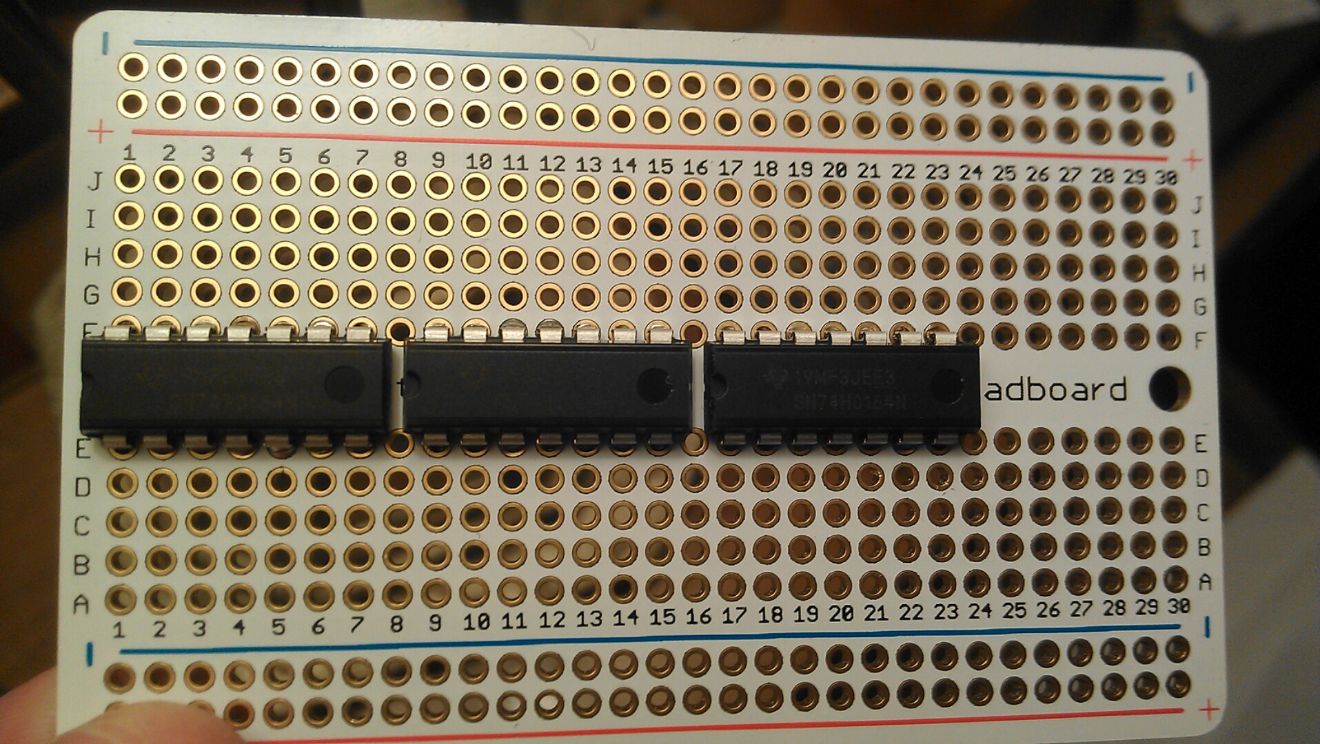
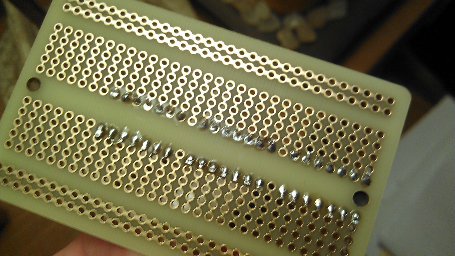
Sorry for droning on there, but I'm not even sure I adequately explained it. I also did some soldering today, although it is just the first part of much more to be done.

If you can read the schematics above, you'll see I plan to use the 4 total rails for positive, ground, clock, and clear lines to run to the shift registers. The input of the first will come from the arduino, and its output will feed into the input of the second. This is called cascading, as the bits that run over in the first shift register trickle down the second, and same for the third. I will also have to run a latch wire somewhere, but that is trivial. I hope the ICs work, I soldered as quickly as I could. I know I should have used a socket, but it just looks so pro without, lol

The next thing for me is to find the mount I'm going to use, so I can start getting the project laid down to it's final form.
 j0z0r pwn4tr0n
Discussions
Become a Hackaday.io Member
Create an account to leave a comment. Already have an account? Log In.