Irene Wolf
Cone Winder Software uploaded on github (19.12.24)
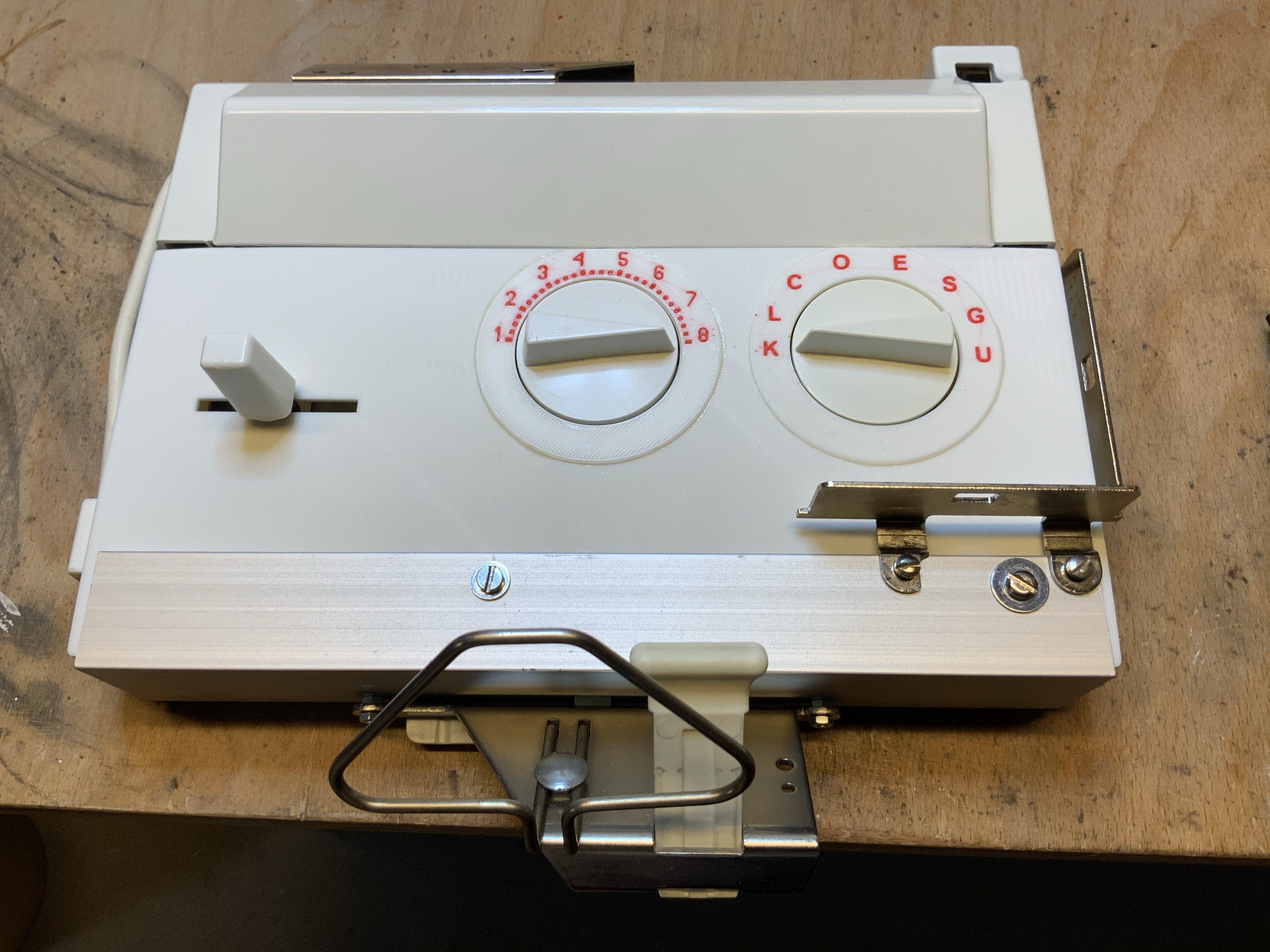
I have built a cone winder (based on the concept of Schönflies Motion) because commercially available cone winders for hobby knitters often fail to wind yarn flawlessly. This can cause significant issues when using electronically controlled knitting machines with motors. To address this, I designed and built my own cone winder.
The cone winder has been operational since early 2023 and works perfectly. It supports cones and cylindrical spools of various sizes. However, it is still missing sensors to detect the left and right endpoints and a button to stop the motors manually.
The yarn I use measures normally between 15,000 meters to 30,000 meters per kilogram.
The project is still in progress.
The control software for the cone winder (using Bresenham's Line Algorithm) is now available on github: https://github.com/IrenePassap/Cone-Winder-Control-Software/tree/main
Yarn Winder - Cone Winder, new Video on youtube (6.2.23)
The XY axes move like the TBot (see the video below).
Video TBot
New Video on youtube (29.12.21)
The Video shows the setup, how I write a simple Jacquard technique in part 1. The second part shows how the machine knits and the swatch.
I will upload the new software version in the next few days on Github. I've revised the code and the GUI. I have also improved the error messages.
Passap E6000 is a computer-controlled knitting machine. It has two needle beds. Each individual needle on the front needle bed can be controlled via a console. The needles on the rear needle bed are controlled mechanically. I have always dreamed of being able to control the rear needles via the computer as well. I knew it was somehow possible but had no idea how. The essential idea came from Hackerspace Bamberg (https://www.hackerspace-bamberg.de/Passap_pfaff_e6000, https://github.com/knitty/firmware/tree/master/software/Knitty ). The hackers have exchanged all parts from the back-needle bed with those of a front needle bed. For the new rear needle bed, a second front lock has been rebuilt.
_______________________________________________________________________________________________________________
Juni 2021 New Version
_______________________________________________________________________________________________________________
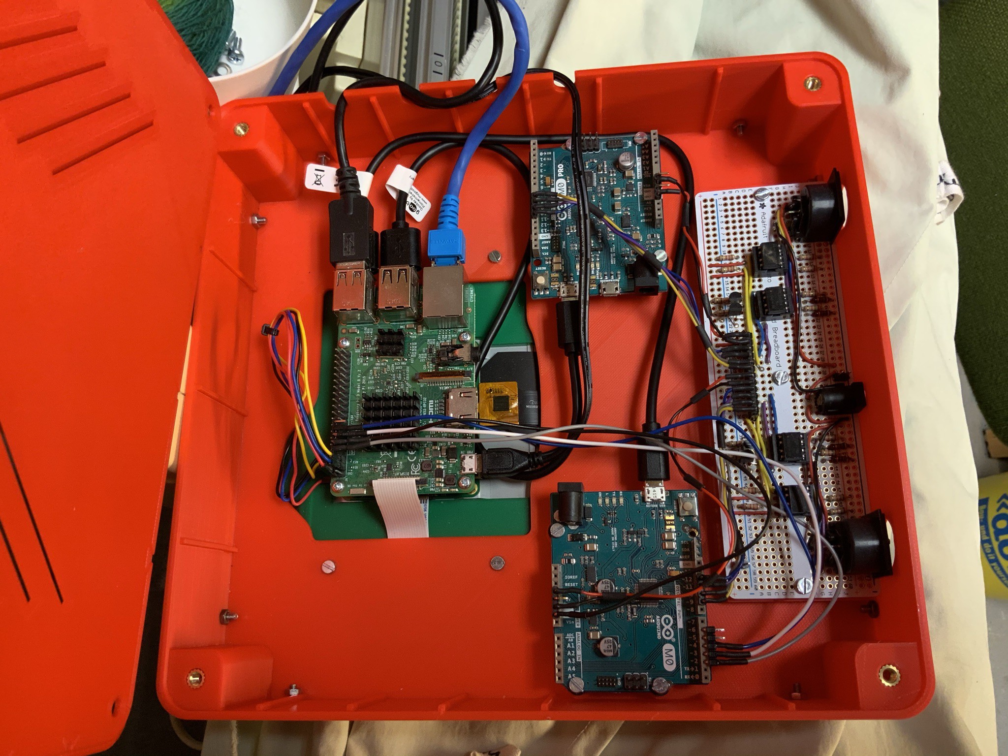
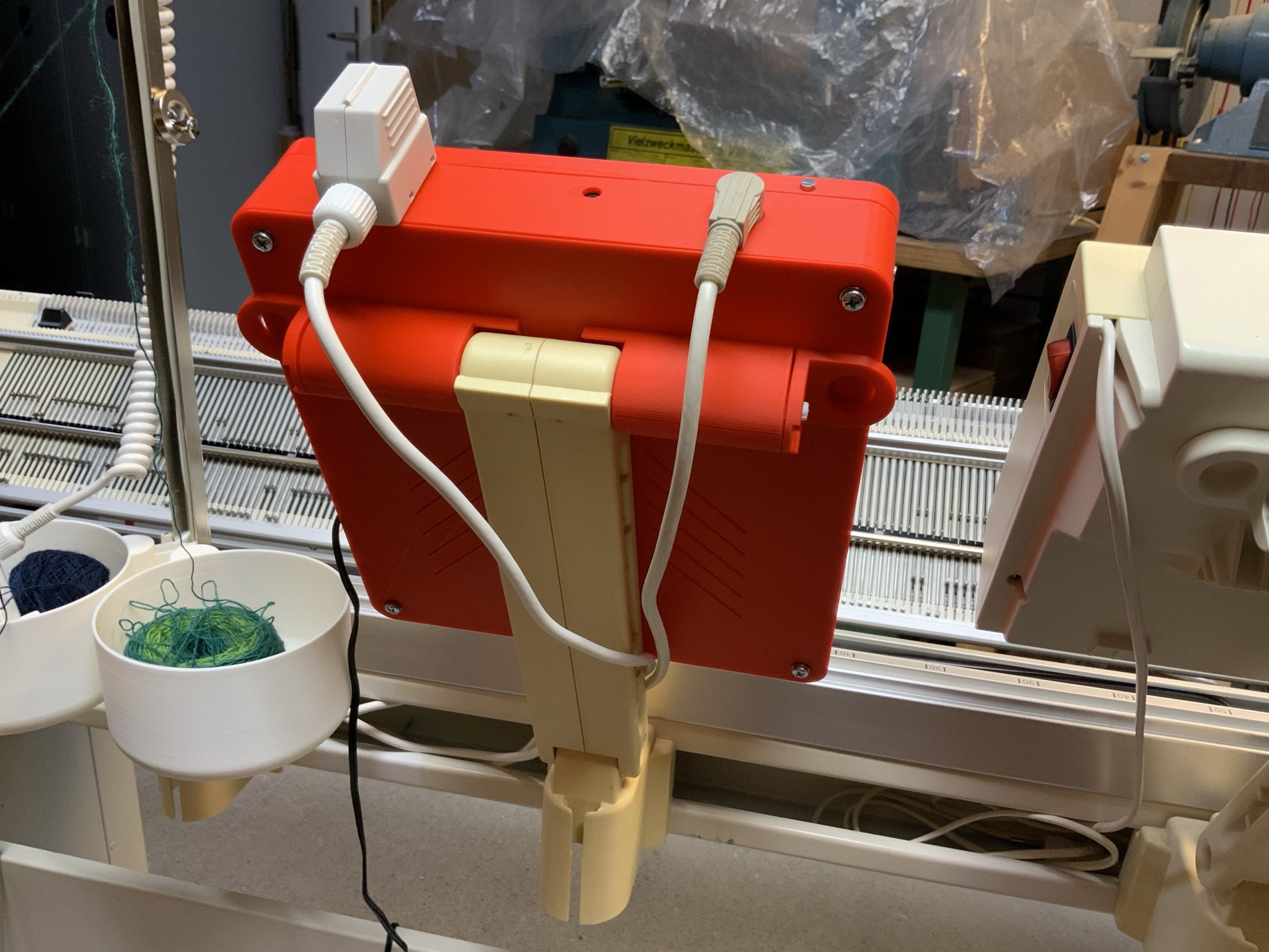
Video and photos of the console, the motor controller unit and interface.
If you would like to find out more, just ask.
Same mounting as the original console
Back of the console
Rear lock
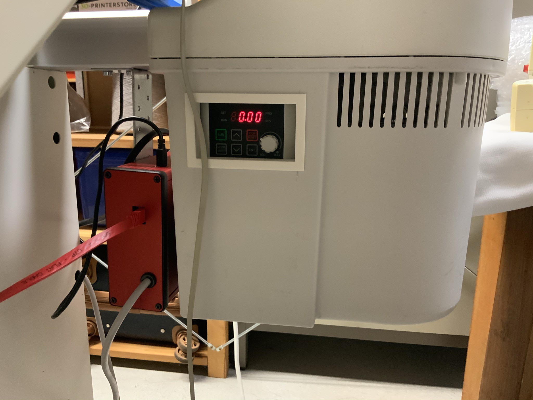
Motor, window for the frequency converter. On the left: Motor interface. Black cable on the top of the red enclosure is the USB connection to the console.
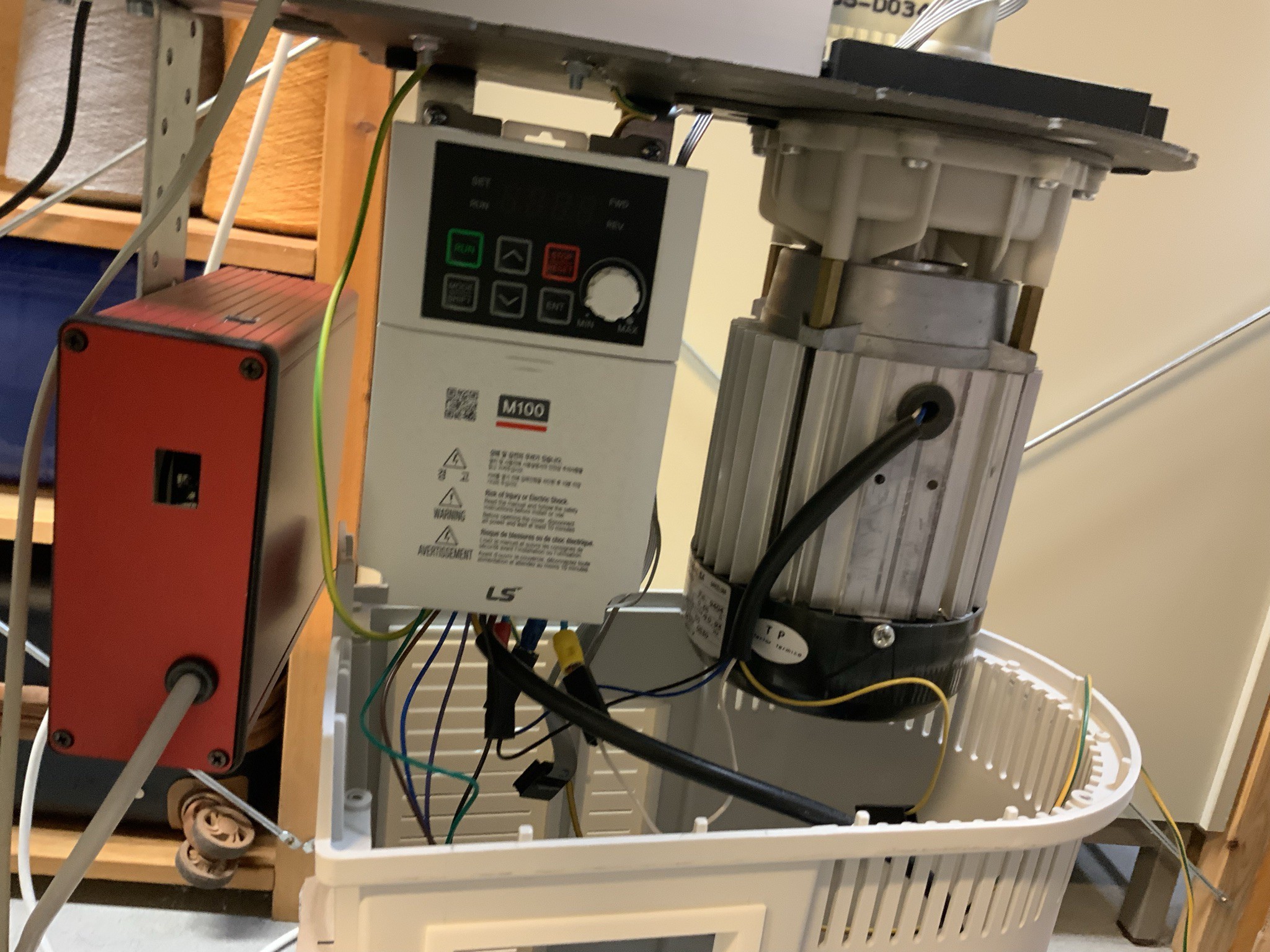

frequency converter
Mounting frequency converter
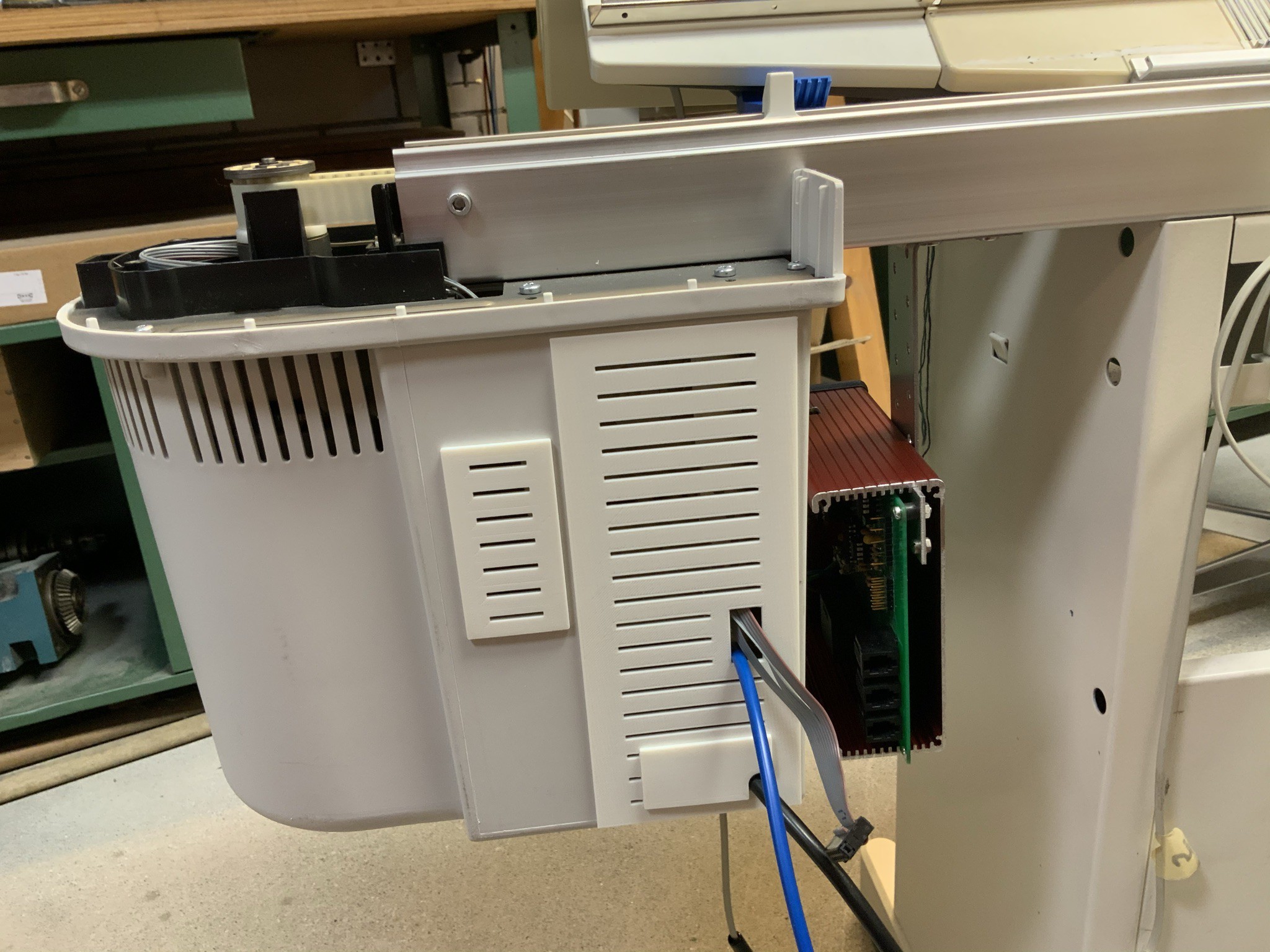
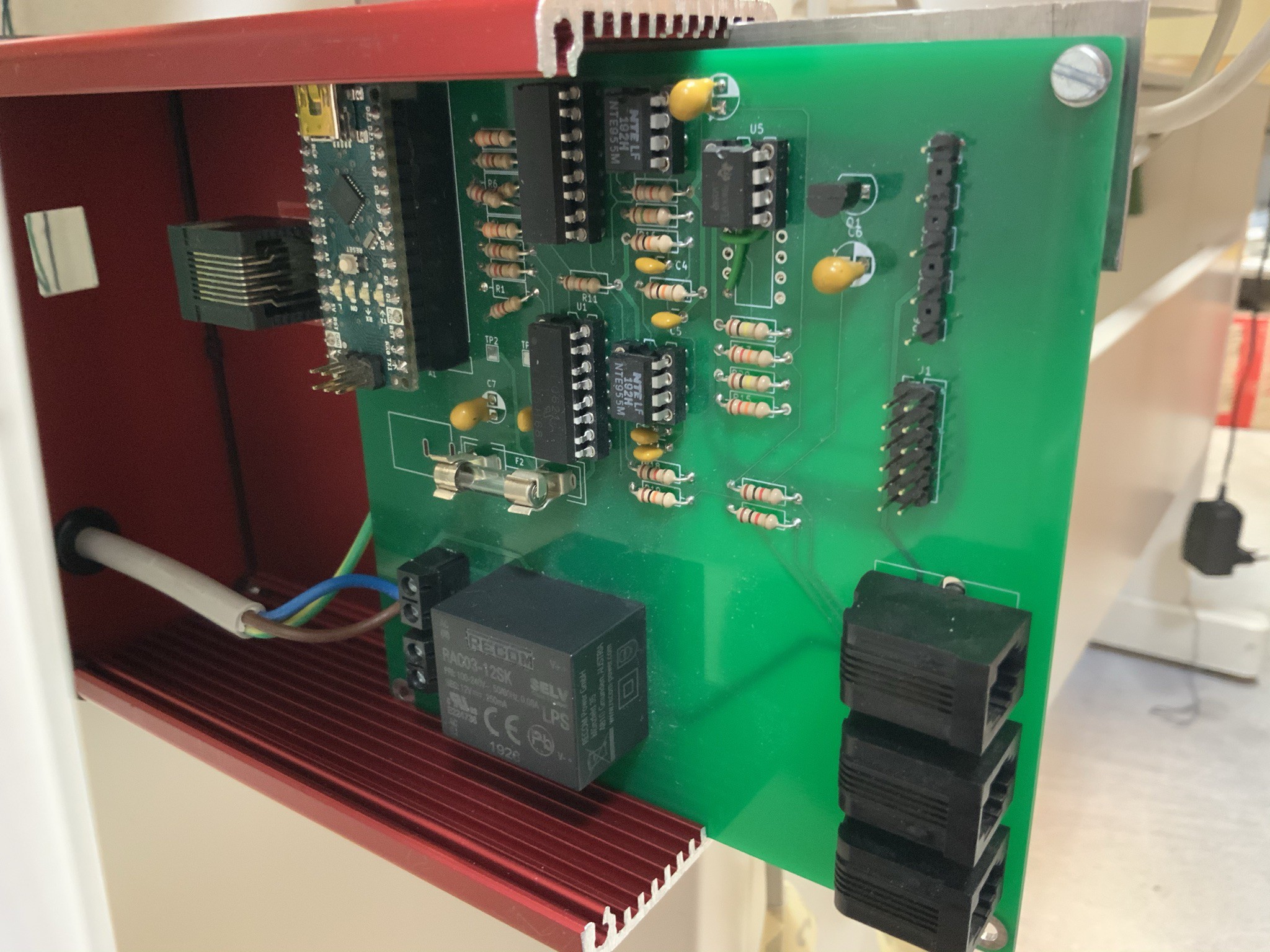
Motor interface. Owen made the design of the board according to the previous interface, thank you Owen, the interface looks now much nicer. The Arduino is now on this interface.

___________________________________________________________________________________________
Passap Electra 4600 rebuilt (2020)
____________________________________________________________________________________________
In the video below (2020) you can see the knitting machine and the motor Electra 4600 in action. More detailed information will follow over the next few weeks.
What is new?
The electronics of the Passap Electra 4600 motor have been replaced by a frequency converter, an interface and a controller. More project details will follow over the next few weeks. The latest version of the software will be published on Github. I hope this information will help you to realize your own project.
Electra 4600 connected to the frequency converter
I actually wanted to integrate the Electra 4600 engine in my project. Unfortunately the Electra 4600 engine had malfunctions. The control circuit board was damaged. We couldn't find out if more was broken. For example, the linear voltage regulator (REG 1) got very hot.
Since the board is very expensive, My husband came up with the idea to control the motor via a frequency converter. As tests showed the motor works wonderfully with the frequency converter.
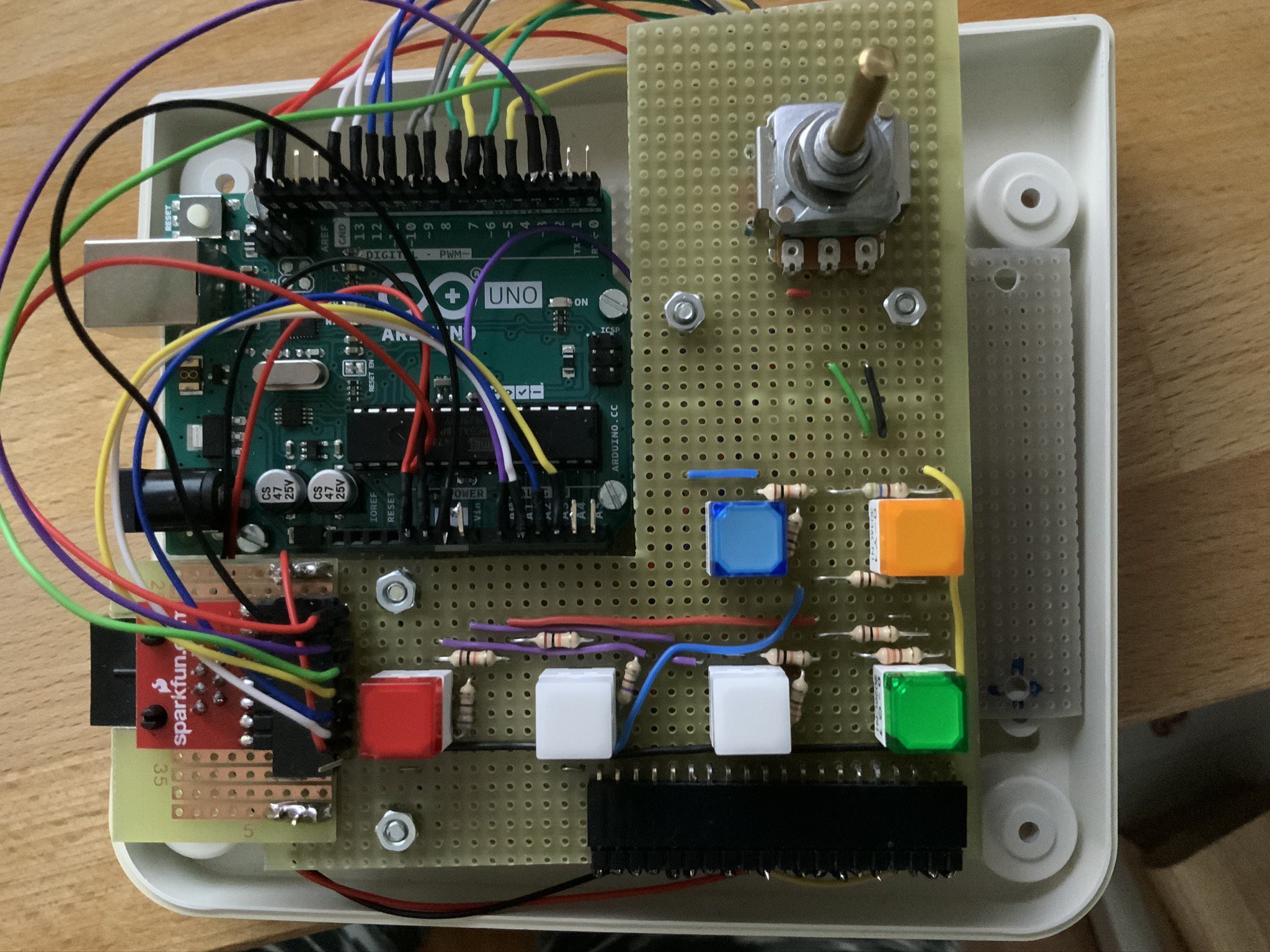
Now the motor is connected to a frequency converter. A newly built controller drives the frequency converter via an interface. The controller essentially consists of an Arduino Uno, LEDs and switches. The controller is connected to the interface via an RJ45. The RJ 11 sockets for the yarn break detection and autocolor (detects if more than one eyelet is up) are on the interface and produce an emergency stop if an error occurs.
The reset button is on the controller. The new controller will be monted on the original location (the upper part of the box is not yet printed). I can regulate the speed manually using the potentiometer and automatically via the Raspberry Pi software. In this way it is possible to keep the speed constant when changing colors, regardless of how slow or fast the motor otherwise runs.
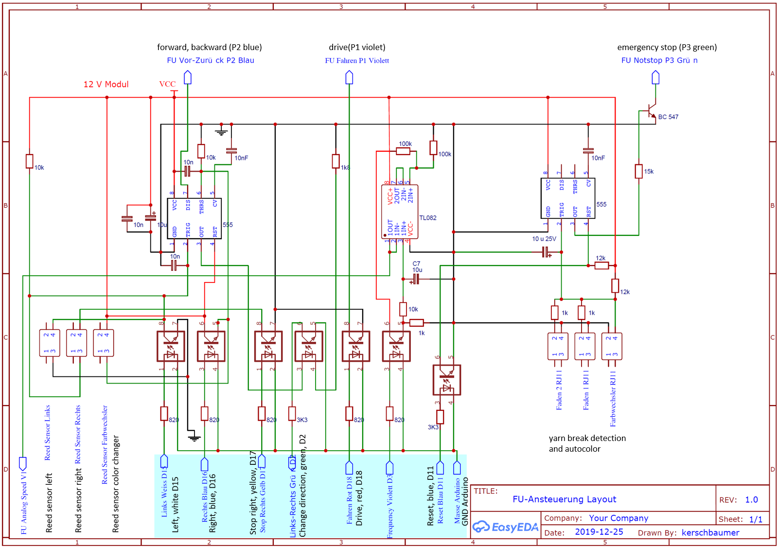
I have uploaded the "Service Instruction for motor drives of electra 4" and the scheme of the interface.
The Software is uploaded on Github, click link below:
Software Project Passap-E6000-hacked-and-rebuilt
Project description
In summer 2017, I also rebuilt my knitting machine. This worked well except for a few minor things.
I also wanted to replace the console. However, Hackerspace Bamberg's solution
does not work for me. It is unstable. I am a knitter. Therefore, the machine
must always work perfectly.
I chose a slightly different way. The knitting machine has been running error-free so far. In the VIDEO you see the knitting machine in action.
In my opinion there are several ways to control the knitting machine. I would like to point out only three central points, which should be considered regardless of the chosen path.
A first important point
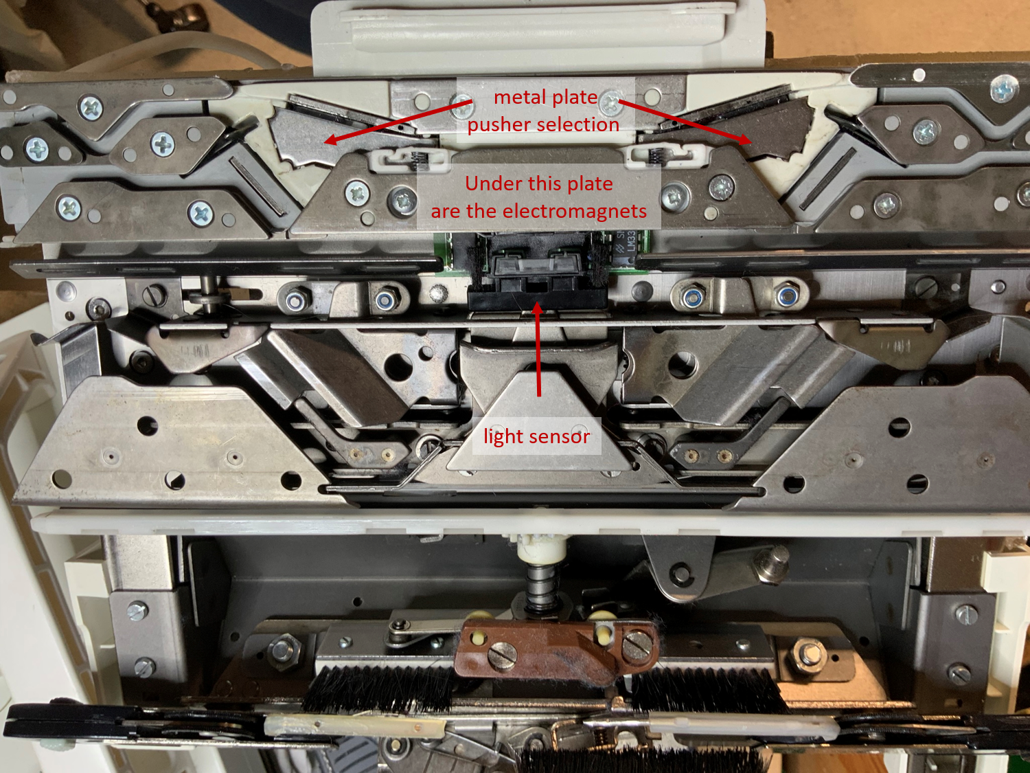
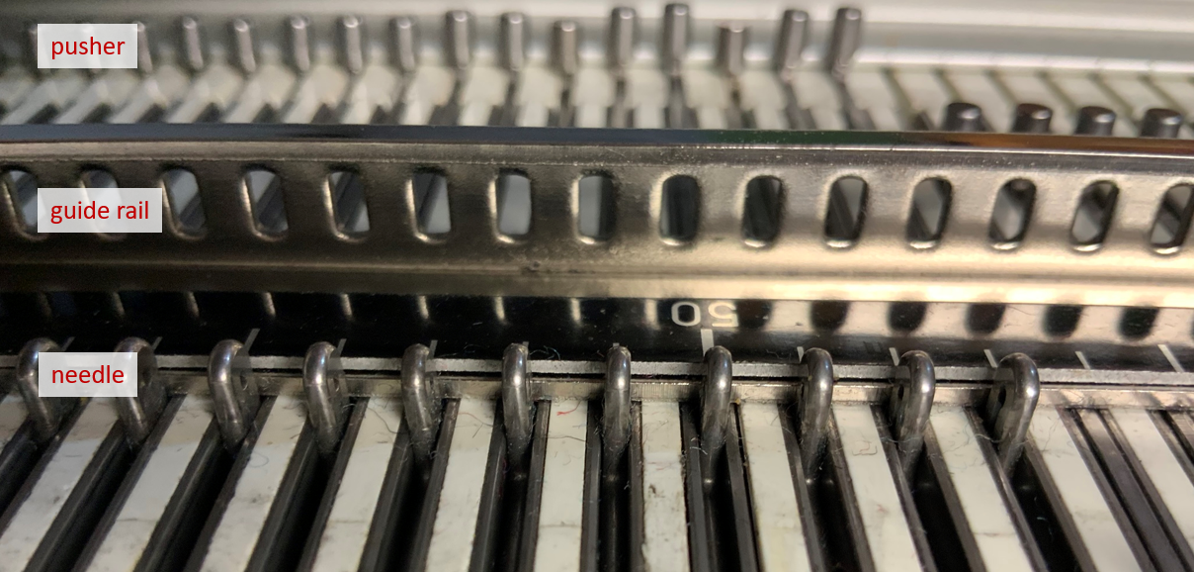
The lock has two light sensors with a distance of 14 mm. The light sensors are moved over the guide rail, which has 2 mm wide holes at a distance of 3 mm. The 5mm correspond to a needle. When the lock is moved over the needle bed, the two light sensors produce a distinctive pattern due to the distances between the light sensors and the spacing of the holes on the guide rail. The position and direction of the lock can be determined by this pattern. Depending on the pattern, the electromagnets are switched on or off. As a result, the magnetic field of the metal plate next to the electromagnets is reversed. Depending on the polarity, the pushers are positioned. The position of the pushers determines which needles are selected and which are not.
Unlike Hackerspace Bamberg, I programmed two interrupt routines for each lock. Why? Depending on the speed, there are more or less false selections if only one interrupt routine has been programmed. In order to work stably, two interrupt routines are required for each lock (one routine per sensor). I assume that the programmers of Passap used all the information from the sensors to register the exact position of the lock, regardless of the speed and movements during the knitting process.
Which information of the sensors do I use for my project? As soon as the status of a light sensor changes, the associated interrupt routine is triggered. Then the condition of the two light sensors is measured. Overall, eight patterns can be distinguished on this way.
The state of sensor A has changed, interrupt routine A is triggered: Sensor A on - sensor B off; sensor A on - sensor B on; sensor A off - sensor B on; sensor A off - sensor B off
The state of sensor B has changed, interrupt routine B is triggered: sensor B on - sensor A off; sensor B on - sensor A on; sensor B off - sensor A on; sensor B off - sensor A off
///////////////////////////////////////////////////////////////////////////////

// Interrupt Routines

///////////////////////////////////////////////////////////////////////////////

// Pin CSENSE (light sensor) has changed state and triggered an interrupt
// The switch statement in the loop method requires unique cases. Therefore, I add 3 to the state of the
// light sensor CREF and multiply the result by 10. Thereafter, the state of
// the light sensor CSENSE is added.
// In this way, 4 different codes can be generated: 30, 31, 40, 41

void interrupt_CSENSE() {

  interrupted = true;  //flag

  crefNow = digitalRead(PIN_CREF);
  csenseNow = digitalRead(PIN_CSENSE);
  state = ((crefNow + 3) * 10) + csenseNow;
}

// Pin CREF (light sensor) has changed state and triggered an interrupt
// The switch statement in the loop method requires unique cases. Therefore, I add 1 to the state of the
// light sensor CREF and multiply the result by 10. Thereafter, the state of
// the light sensor CSENSE is added.
// In this way, 4 different codes can be generated: 10, 11, 20, 21

void interrupt_CREF() {

  interrupted = true;  // flag

  csenseNow = digitalRead(PIN_CSENSE);
  crefNow = digitalRead(PIN_CREF);
  state = ((crefNow + 1) * 10) + csenseNow;

  if(state==10){
    if(needle>=0) {
      needle = bitRead(patternArray[patternPos/8], 7-(patternPos%8));
      digitalWrite(PIN_NEEDLE_RTL, needle);
      }

    currentCursorPosition += 1;
    patternPos +=1;
  }

  if(state==20){
    currentCursorPosition -= 1;
    patternPos -= 1;
  }
}
When the lock is pushed from right to left, it creates a distinctive pattern. This pattern is 100% different from the pattern created when the lock is pushed from left to right. Each direction repeats four combinations of sensor states. Since the order in each direction is always exactly the same, the direction and position can be determined precisely.
You can find my program code at https://github.com/IrenePassap/Passap-E6000-hacked-and-rebuilt
A second important point
It absolutely needs two Arduino. Why? The two needle beds can be moved against each other. If I knit fast, I need something between one and two seconds per row. Per lock and row, a maximum of 800 interrupts (4x200) are triggered. Depending on how the needle beds are facing each other, the interrupts on the front and back needle beds are triggered almost simultaneously, which can lead to errors if only one Arduino is used.
In my opinion, the interrupt routine should be as short as possible, considering the number of interrupts.
A third important point
Anyone who knits knows that the pattern and technique have to be programmed separately. Why? A pattern can be knitted in very different ways. The way the pattern is knitted is often referred to as technique.
My Project
For my project I used two Arduino M0 and one Raspberry Pi 3.
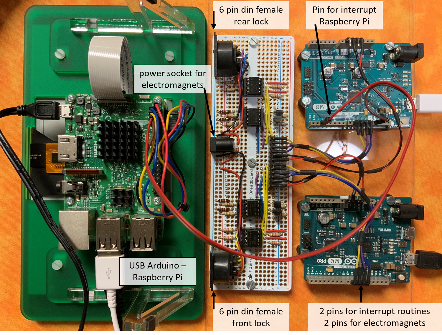
The two Arduino receive instructions from the Raspberry Pi via CmdMessenger. The Arduino are responsible for reading the sensors, switching the electromagnets on and off, determining the position and direction, as well as setting the pushers. When changing direction, an Arduino sends feedback to the Raspberry Pi (programmed as an interrupt in the Raspberry Pi). The Raspberry Pi imports the pattern file and the technique file. All data is backed up in SQLite.
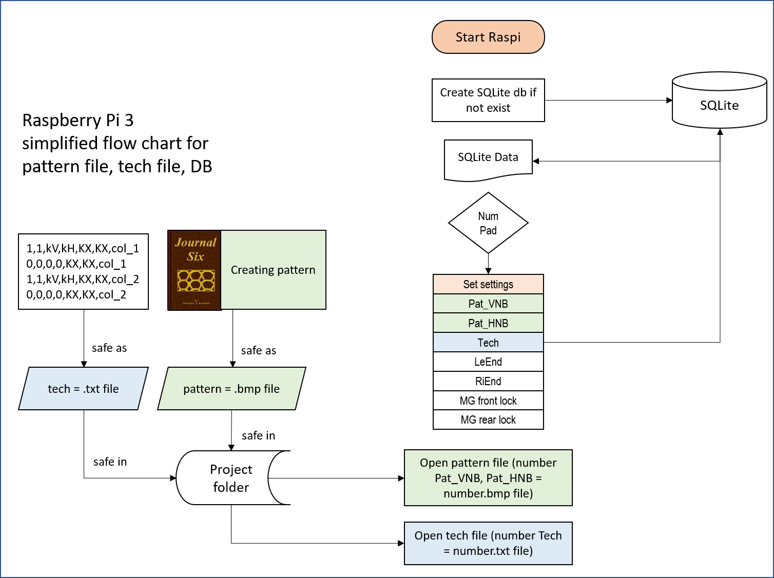
When changing direction, depending on the selected techniquea a new pattern row is sent to the Arduino. The knitted pattern rows are counted. Through a graphical user interface, I can enter values for different variables. In addition, instructions and value changes are displayed during the knitting process.
Video graphical user interface: https://www.screencast.com/t/rP4bmxYhw
I have knitted some objects since July 2018, for example the almost finished knit modell below. The knitting machine works reliably and without errors.
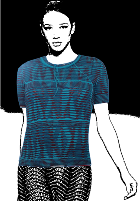
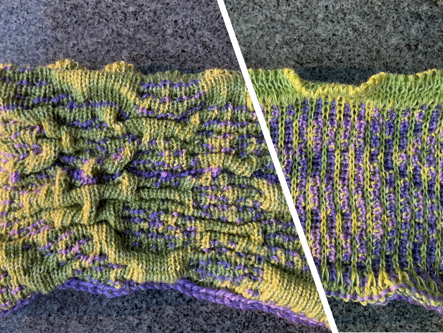
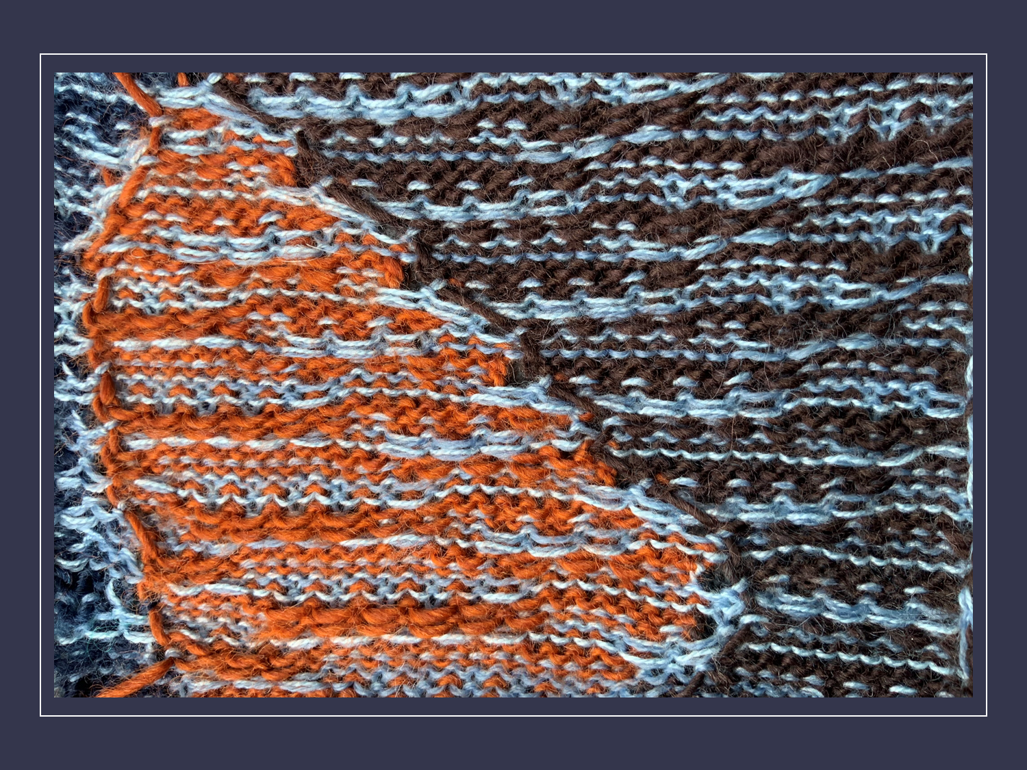
Some swatches
I have so many options. The challenges now lie in designing good patterns and techniques. Not all ideas work. Below are some swatches.
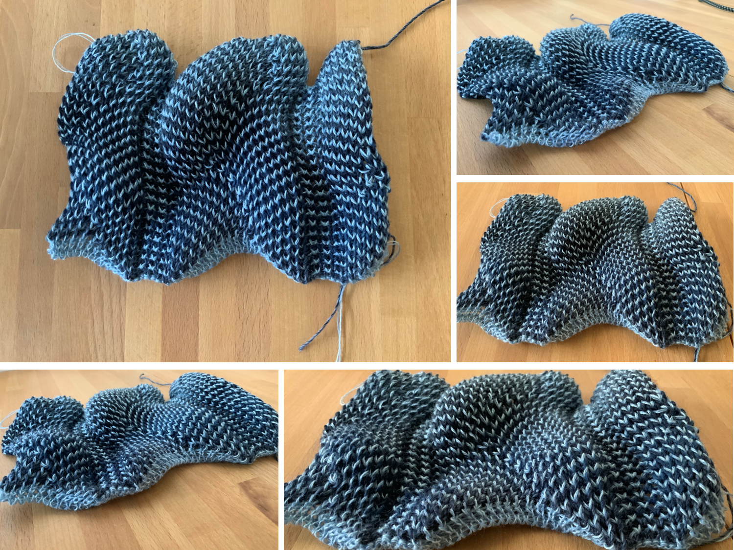
Short row, front and back view
Pleats, front and back view
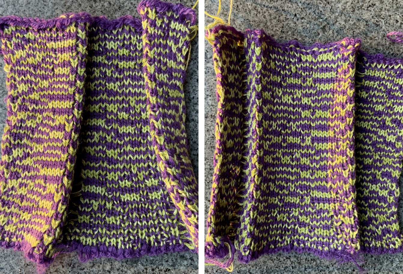
Pin Tuck, front and back view
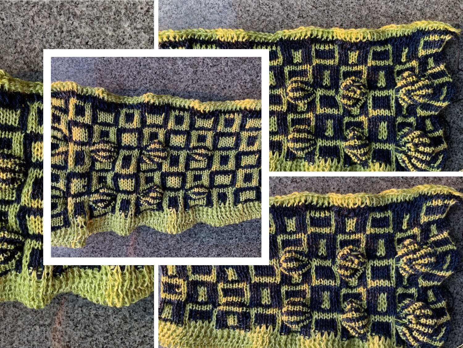
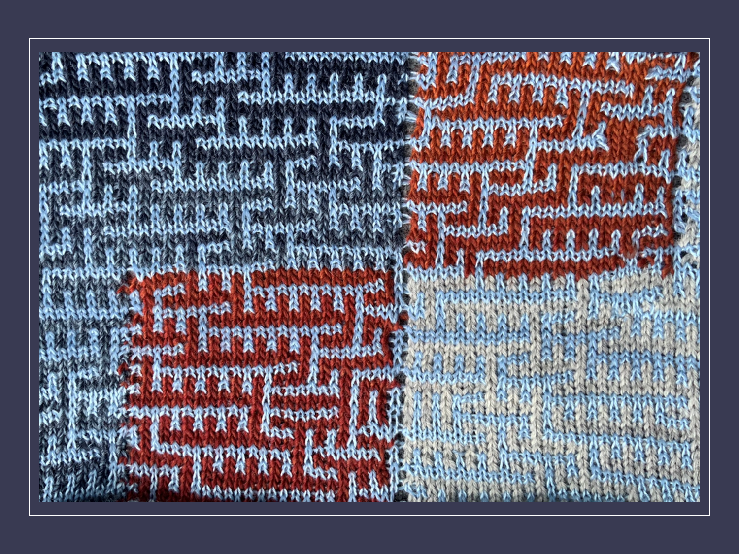
3 Colour slip stitch swatch knitted on the front needle bed only
After a software update, the following patterns are easier to generate. It was always possible to design the patterns for the following swatches, but it was quite complicated.
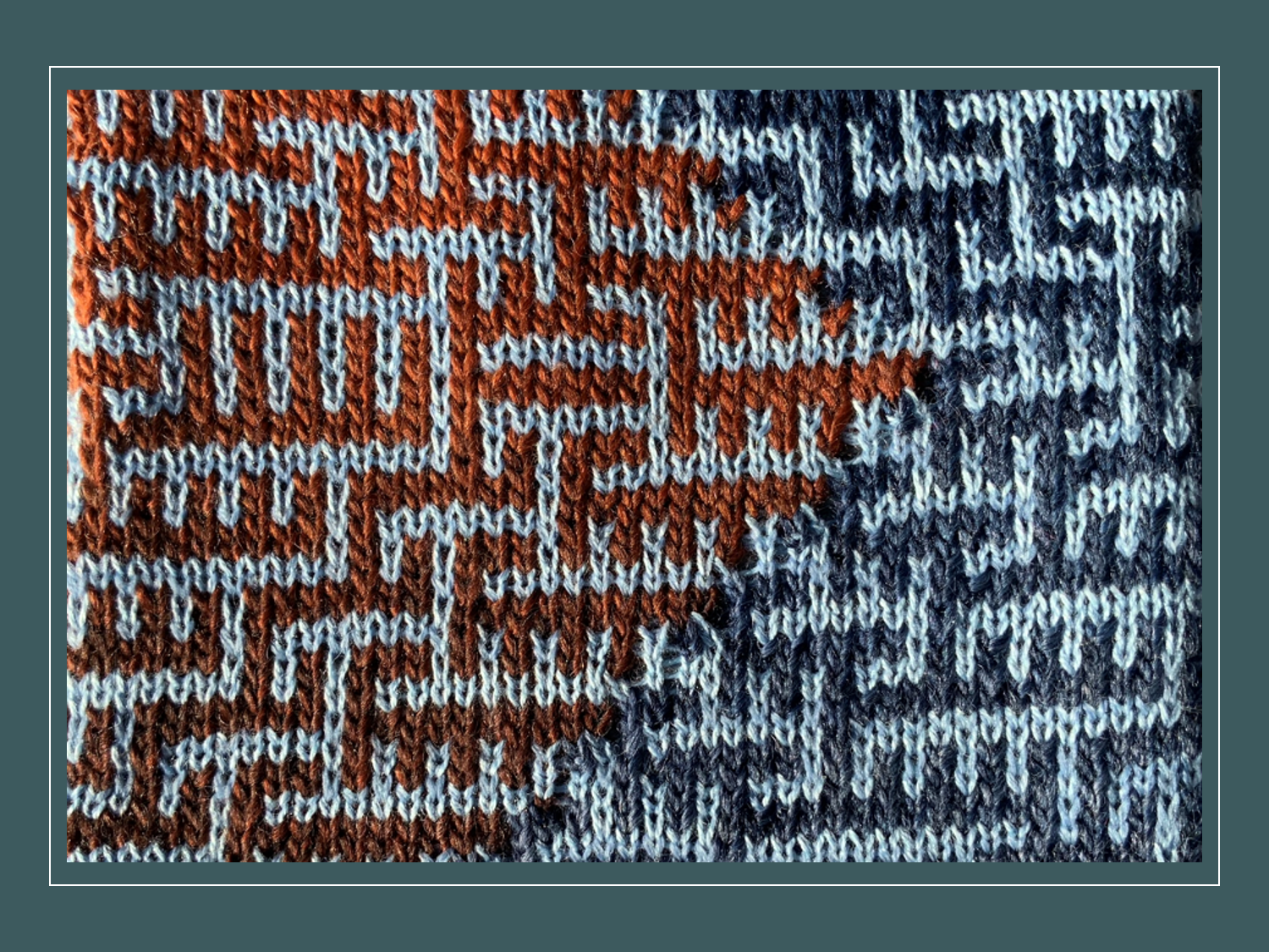
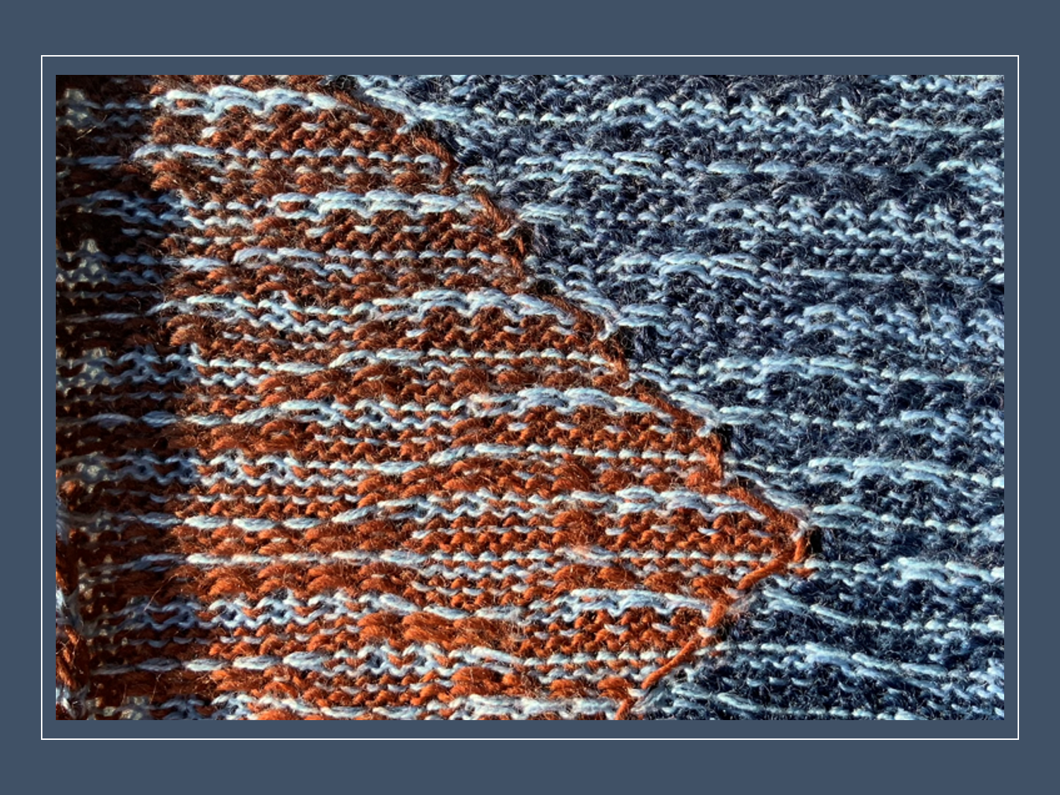
4 Colour slip stitch swatch knitted on the front needle bed only
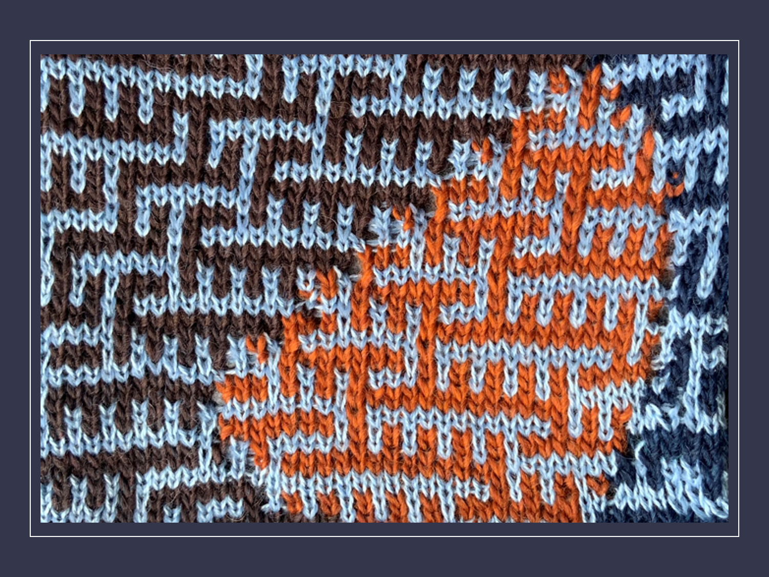
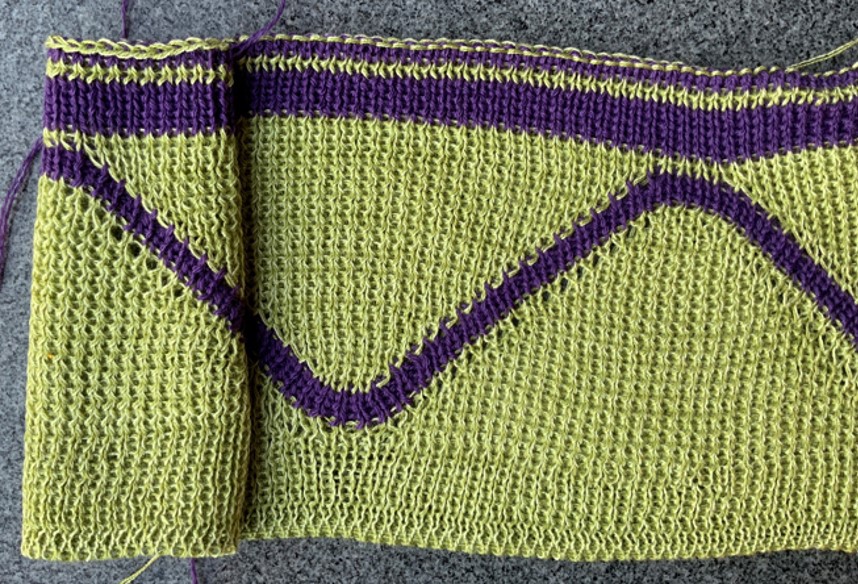
My favorite pattern
The picture shows a 3D Chevron pattern, which is partly knitted on the front and back needle bed (KX / KX = tuck / tuck) and partly only on the back needle bed.
This pattern can not be knitted with the Passap E 6000. Unless you put the pusher on the back needle bed by hand.
New rear lock cover
- None of the covers fit for the rear lock
- In the picture below you can see the new cover of the rear lock. I had The 3D printing was not perfect, I had to fix some places. That's why I do not upload the CAD. If someone still wants the CAD, let me know.
The project is not finished yet
The Passap E6000 has many built-in features. Among other things, forms can be entered. I will program all the essential features of the original Passap console step by step.
- As you can see in the Picture above, there is still no nice solution for the spiral cables. This is part of the summer Project.
- Currently the Passap Motor Electra 4600 is not in operation. I will start this part of the project in summer.
I want to say thank you
Thanks to the published experiences of many others on the Internet, I was able to successfully implement my project.
I'd like to give special thanks to ptflea from Hackerspace-Bamberg for sharing his experiences. Without his project description and the publication of his program code on GitHub I would never have been able to realize my project.
I would like to return something with the publication of my own project.
How to reverse-engineering back needle bed and rear lock Passap E6000
As I already pointed out, I used the information on the Hackerspace Website for the reconstruction of the rear needle bed and the new rear lock.
https://www.hackerspace-bamberg.de/Passap_pfaff_e6000
Since the information is written in German, I briefly describe the process here. However, it is important that you already have some basic knowledge about the knitting machine or you can get them. Pay close attention to how each part is positioned. Take time for photos and notes, which makes the reconstruction easier. Unfortunately, I did not take enough photos and notes, so I had to invest a lot of time to find out the exact location and how to move or rotate the parts.
Passap E6000 back needle bed reverse-engineering
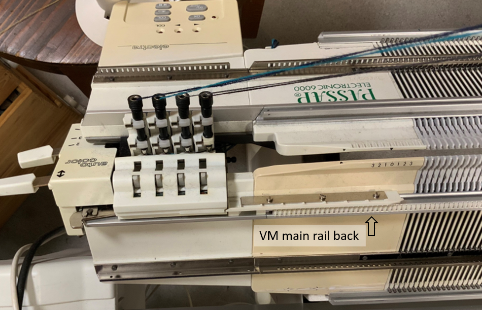
You have to replace the parts of the rear needle bed with parts of a front needle bed. The needle channels, plastic needle beds, the rails and the pushers of the back metal needle bed would not work anymore with a front lock. You do not have to disassemble the metal needle beds like Hackerspace did. You only have to remove the parts on the metal needle bed on the back. Then you have to replace most parts with parts of a front needle bed.
The VM main rail back remains and all parts that are important to the function of the color changer and the VM Driver of feeding eyelet.
By the way, this is a good opportunity for deep cleaning the knitting machine because you have to do practically the same work. In the Passap Paramedic by M. Becker you will find many helpful tips.
The photo below shows the back needle bed after the reconstruction. As you can see most parts are from a front needle bed.
Passap E6000 look reverse-engineering
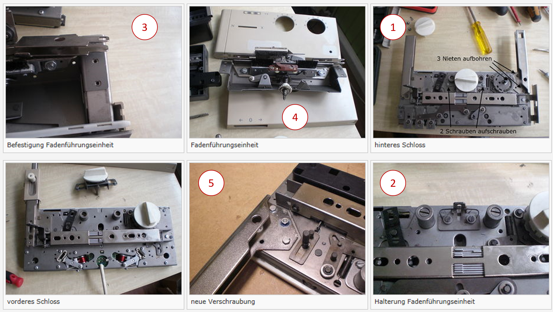
Picture 1-6 are from Hackerspace Bamberg
See also: https://www.hackerspace-bamberg.de/Passap_pfaff_e6000
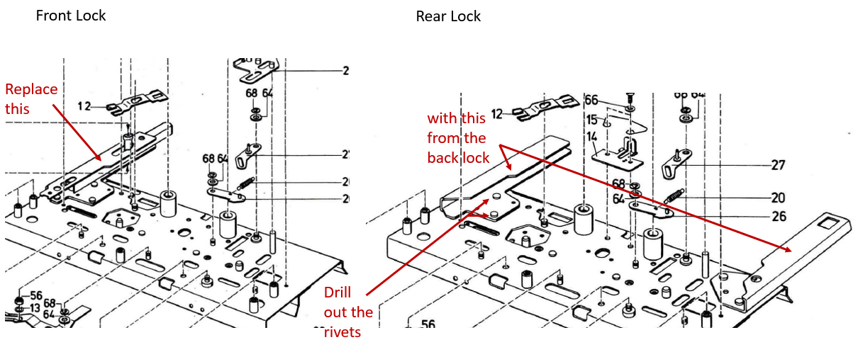
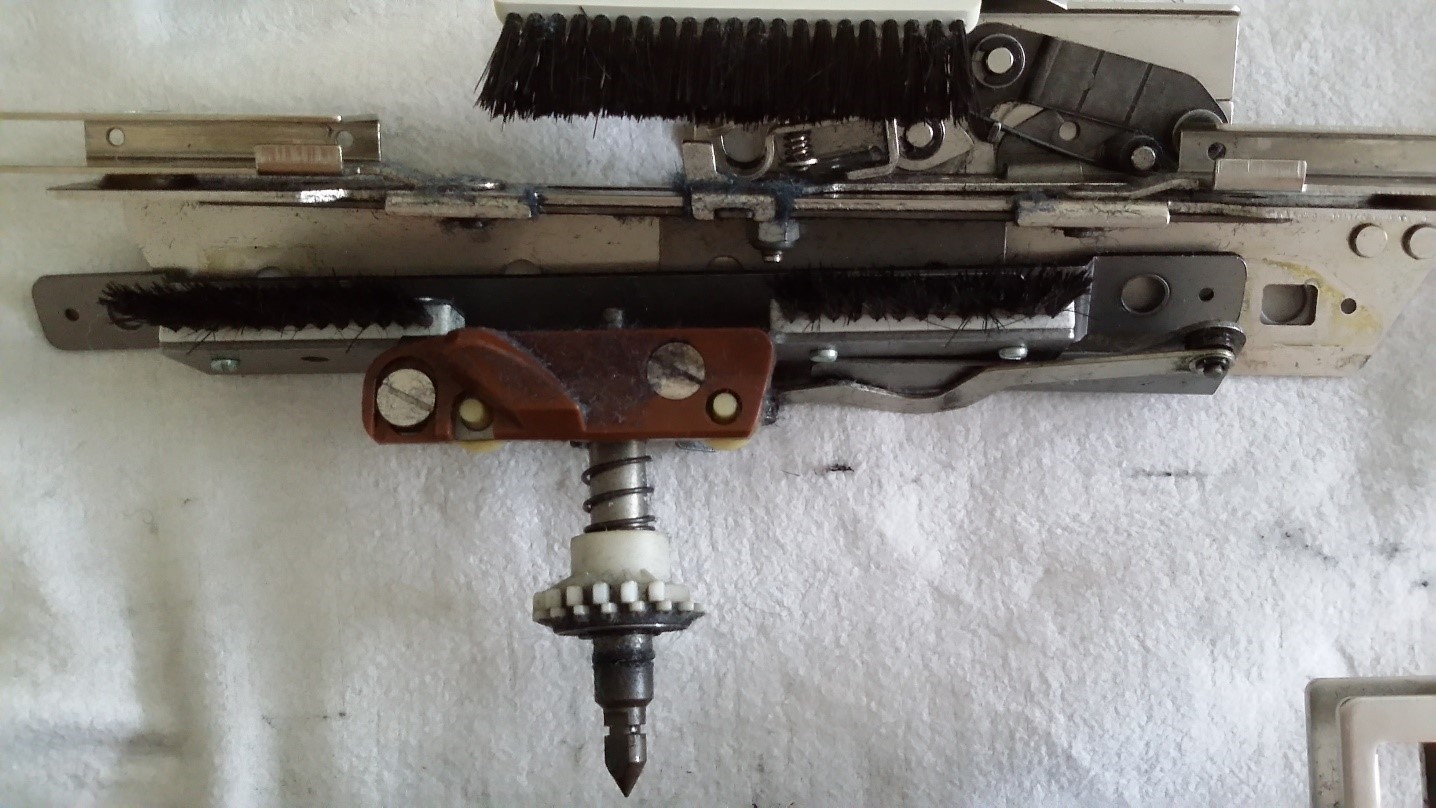
Picture 1, rear lock: Unscrew the two screws (Schrauben aufschrauben).
Picture 2, 7 and 8 below, rear lock: Unscrew the two screws.
Picture 3, 4, and 9 below, rear lock: Remove the screws from the “VM Driver of feeding eyelet” and remove it as a whole as shown in the picture.
Picture 5 and 10 below, front lock: Replace the metal bracket on the front lock with the two brackets on the rear lock. Use screws and locknuts.
Now you can mount the VM-Drive of feeding eyelet on the front lock.
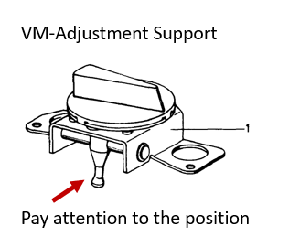
Picture 11: Pay attention to the position of the VM adjustment support.
 Picture 7
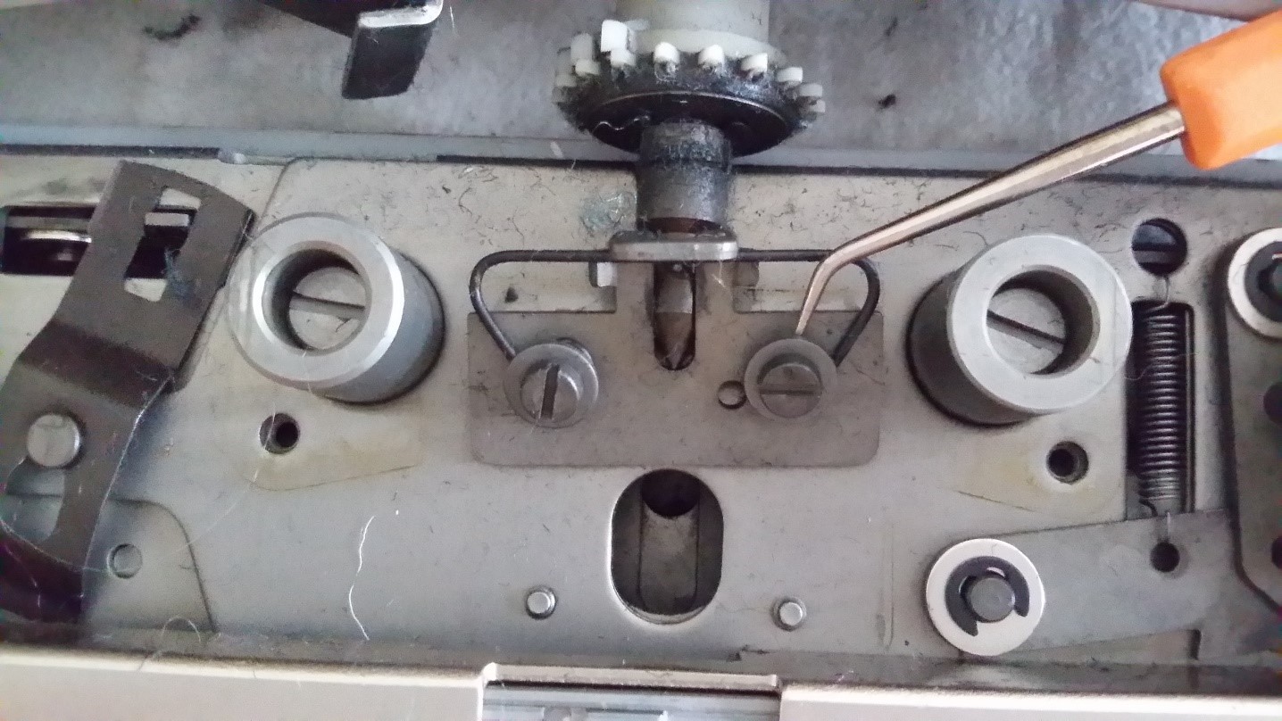 Picture 8
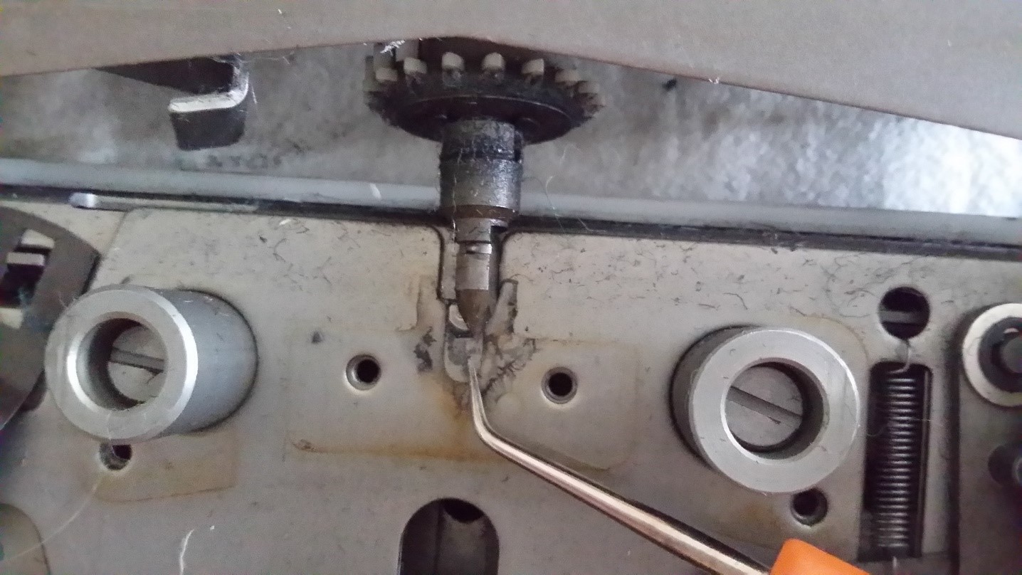
Picture 9
Picture 10