Close
0%
0%

Polymorphic I2C Shield for Arduino MKR

This is a shield for the Arduino MKR to provide multiple I2C ports for the new form factor. Supports Grove, 0.1" top, bottom and sideways.

Public Chat
Similar projects worth following
This is a shield for the Arduino MKR to provide multiple I2C ports for the new form factor.

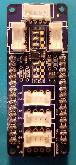
It supports a variety of configurations including Grove and/or 0.1" Molex type connectors above or below the MKR board, straight and/or sideways connectors, 3.3V and/or 5V, and can carry an optional I2C EEPROM chip (because the MKR series don't have EEPROM).

This is prototyped and tested and I'm ordering parts to add it to my Tindie store.


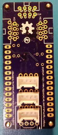
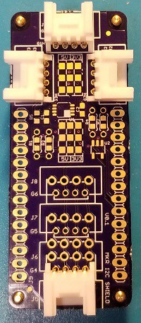
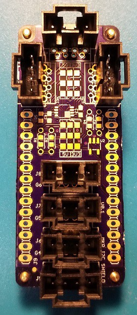
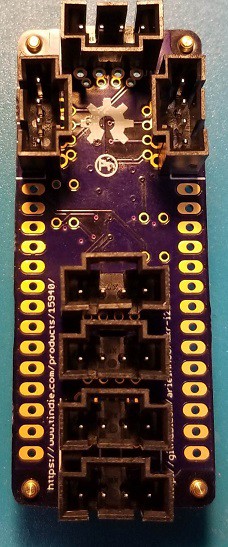
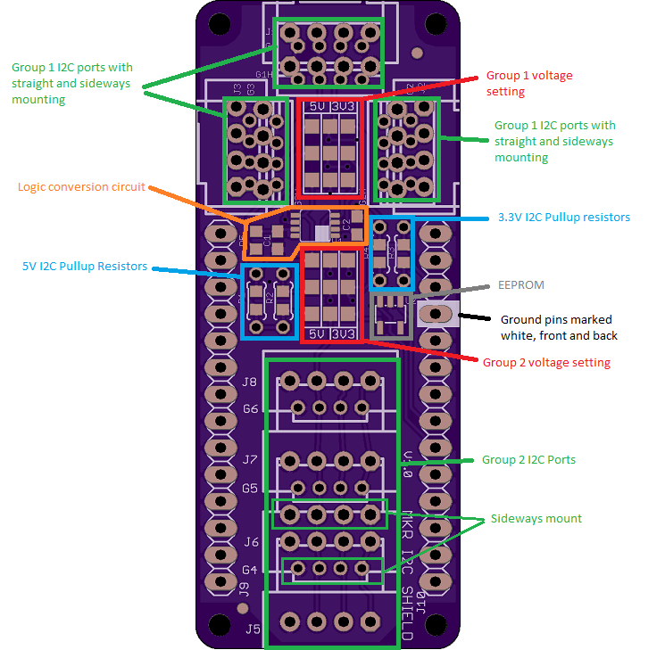
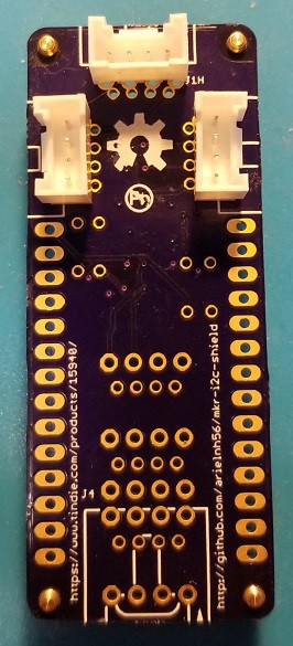
The connector mounting locations include 6 locations for Grove and 7 locations for 0.1" - specifically spaced for the locking Molex SL connectors. In each style 4 of the positions have an offset set of holes for the 90 degree "sideways" versions. This does give the board a bit of a Swiss cheese appearance, but it works.


The ports are divided into two groups and each group can be set to either 3.3V or 5V operation with solder jumpers, and a logic level conversion chip is included. Both the 5V and 3.3V can have separate pullup resistors in SMD or thru-hole forms. As the MKR boards include 4.7k pullups on the 3.3V I2C pins these will be left unpopulated for 3.3V and will be populated with 4.7k for the 5V side. Sometimes 4.7k is not the value you actually need, so this gives you the flexibility to do some tuning.

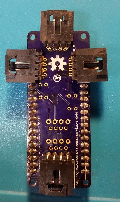
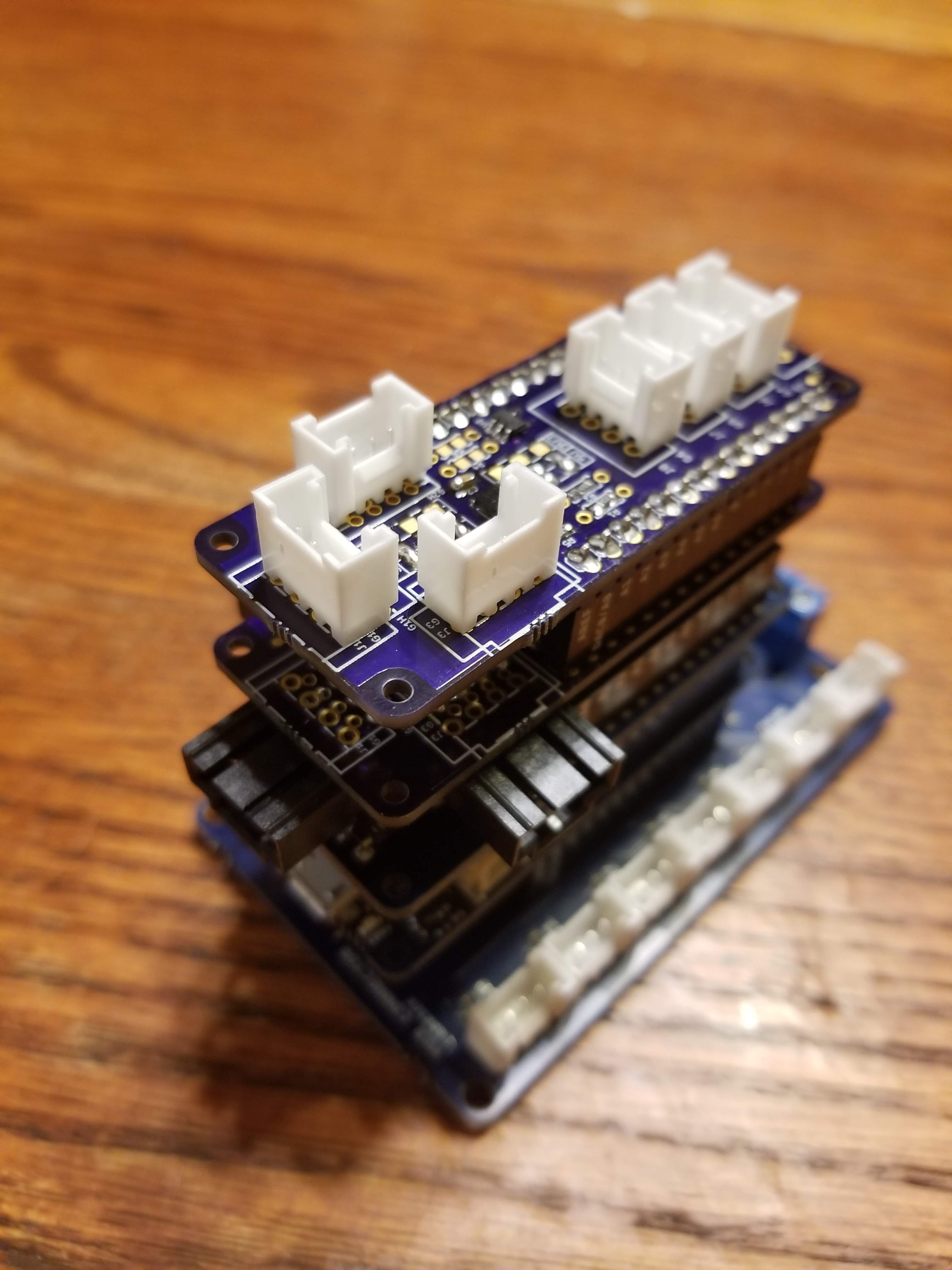
Straight connectors can be mounted on top or underneath the board allowing the board to be on the top or bottom of the stack. The sideways connectors allow it to be used in the middle of the stack with a reduced port count. Due to the polarity of the connectors the sideways Grove connectors must be mounted on top and the sideways Molex underneath. In all stacking configurations I have tried this works fine.

This will be supplied with your choice of connectors and stacking headers. 

As the MKR Arduinos use the SAMD21 chips which do not have EEPROM, a footprint for an I2C EEPROM chip is included.

Connector locations:
Bottom mount straight grove
bottom mount straight grove
top/middle mount sideways grove
top mount sideways grove
top mount straight molex
top mount straight grove
bottom/middle mount sideways molex
bottom mount sideways molex
straight top grove and sideways molex on the stack
top mount straight molex
bottom mount straight molex

  • Small batch now on Tindie

    Alastair Young02/19/2019 at 22:39 0 comments

    Also just received the delivery of printed female headers.

    https://www.tindie.com/products/15940/

  • Testing Jig built - small batch out later today

    Alastair Young02/18/2019 at 19:01 0 comments

    I had all kinds of fun debugging the test jig. I decided not to burn my (expensive) MKR 1010 Wifi for this and substitute an ATTiny841, but that left me with needing a donor 5V and 3V3 supply. Oh, I'll just use a Funduino Nano shield I though. Realizing afterwards that while that does provide a 3V3 supply, it relies on the Nano for the 5V - which is why the current setup is jumpering in a 5V supply from an Uno clone. I do want a supply with the polyfuse etc, not just a raw 5V feed, as by definition the test jig is going to be subjected to shorts etc.

    I also found I had a bad ATTiny841, and my Arduino build environment for ATTiny was mangled. 

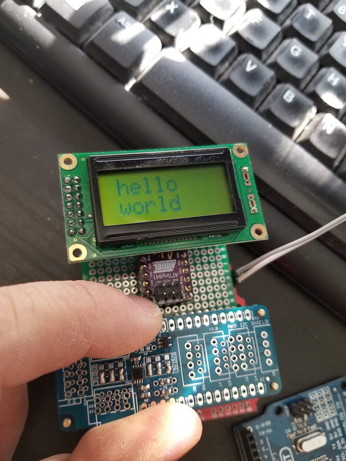
    In the end it all worked out. The jig simply drives an 0802 LCD through one of my I2C adapter boards, and resets it and flashes "Hello World" every second.

    I plan to rebuild it on an arduino proto shield so I can use the power supply from that directly and maybe use the arduino as another I2C target, test other pins etc. The current setup just checks the functionality of the logic converter and the Group 2 outlets. My main concern is that the LSF0102DCTR logic converter has 0.65mm pin spacing - half the spacing I have used on previous projects, so the likelihood of bridging during soldering is higher.

    The jig uses a product board suspended above a proto-boards with pin headers. The protoboard holes are too small for the pogo pins to go through, so that gives a nice hard stop for height. The jig board has no components on it except the 4.7k pullup resistors for the 3V3 I2C bus, which are normally mounted on the Arduino MKR board itself, but missing from the ATTiny841.

    The ATTiny841 board is from the shared space at oshpark. This is a very basic breakout, and I wish it had a footprint for the bypass cap - I'm running out of thru-hole 104's!

    On the supply side the boards arrived very quickly - after Chinese new year ended - and various components and headers and connectors are on order, as are SMD stencils from oshstencils. I have enough parts on hand to make up a few by hand today. The one pictured was pick-and-placed approximately by my thrifty pnp and then manually soldered - after prodding the parts over to the right place. Tweezering is still much faster!

View all 2 project logs

  • 1
    What's on the board and where
  • 2
    More instructions to follow...

    I'll be releasing an initial batch to Tindie later today, hopefully. Documentation writing will also happen today.

View all instructions

Enjoy this project?

Share

Discussions

Alastair Young wrote 02/04/2019 at 19:15 point

Thanks for the feedback. I try and think how people will use my products up front, and work in the flexibility. It saves revisions later. The boards are ordered with some silkscreen improvements from the prototypes shown. It is very easy to solder the connectors in the wrong way (I did that on the very first one and had to desolder and redo) so I'll be aiming to make the documentation as clear as possible.

  Are you sure? yes | no

Alexander wrote 02/04/2019 at 18:53 point

Very nice layout, also glad to see it's open-source hardware! OSH for the win.

I really like your design, it's very attractive and symmetrical. I might have to pick one up!

Cheers!

  Are you sure? yes | no

Similar Projects

Does this project spark your interest?

Become a member to follow this project and never miss any updates