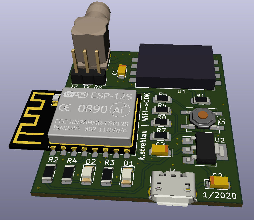
New year, new things!
I decided to completely rework this project with my recent knowledge.
Previous revision had a lot bugs, for example antenna's impedance was not matched to feed. It matched only PA output of my radio module. I decided to replace pcb antenna with SMA connector, which allows user to match antenna on his own.
PCB size has been reduced, all tracks have been moved onto top layer, more vias have been added - it all theoretically should improve device reliability.

Now waiting for PCB fab to do their work :)
 h4rdc0der
Discussions
Become a Hackaday.io Member
Create an account to leave a comment. Already have an account? Log In.