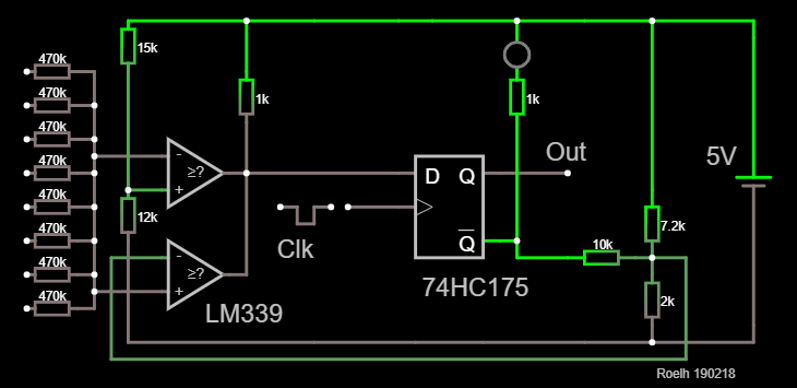
I don't know if the rules forbid the use of a flipflop.... But the state of a cell is digital, isn't it ? So we use digital building blocks for that part.

So a part of the previous design was replaced by a flipflop.
From a practical point of view, it seems logical to place several cells on a single pcb, for instance 16.
Each cell needs 1/2 LM339 and 1/4 HC175, so for 16 cells this is 12 IC's.
The reset input (not in the diagram) of the HC175 can be used to reset the system to all zero. There should also be a possibility to pre-load a certain pattern, or several patterns (to be determined).
Discussions
Become a Hackaday.io Member
Create an account to leave a comment. Already have an account? Log In.
You could save an opamp by making a one op amp schmitt trigger instead of a latch. Not that it really saves you much. I think a schmitt trigger and window comparator circuit would be possible with just two op amps.
Are you sure? yes | no
For an analog system It is cheating with a digital logic chip in it. ;-). Even a clocked D-latch made out of BJTs would be kinda cheating. ;-) But a '175 for sure saves a lot of components...
Putting several cells on a single PCB makes some sense from a manufacturing/ soldering viewpoint , but it will require a bit more PCB area in total. And it will remove the aspect of really seeing that the GoL is made out of small repeated identical cells that are "independent" (or at least only caring about its neighbors are up to).
Are you sure? yes | no