So it turns out Conway's Game of Life is more complicated than I thought. I was under the impression it turns on a cell when there are sufficient neighbors, and turns it off when their are too few neighbors, which is exactly what a 555 timer does on an analog level. Easy peasy.
But apparently it's more complicated than that, in which it turns off a cell if there are too many or too few neighbors, and turns it on if there is an exact amount of neighbors. Which is not what a 555 timer does. Not easily anyway.
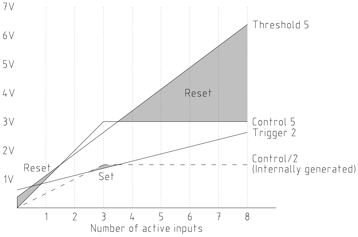
I had claimed this can be done with a single 555 timer, and I won't let a simple misunderstanding of the concept the entire project is based on slow me down. The 555 alone isn't really enough, so I threw in a zener diode to give me some nonlinearity to play with. (I have a few oddball computing projects in the works and have found out just how useful a tiny bit of nonlinearity can be). I made a sort of analog truth table:

The biggest issue I see with this is that some comparisons are only made by 125mV. This should be enough, and can be dialed in by adjusting power supply voltage relative to the zener diode, but it's still a concern. I'll have to prototype something to know for sure whether it can work or not.
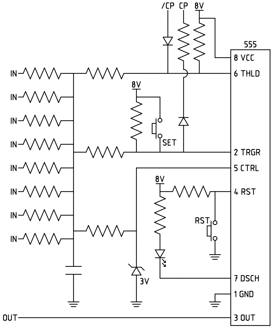
Here is a schematic that should achieve something close to that:

Clocking is handled by holding the comparator inputs too far away from it's other input to ever trigger the flip flop. Setting works by forcing a comparator to trigger the flip flop.
Another obvious problem, is that resistors have to get progressively larger in value for later stages to not affect earlier stages. I'll have to see what the CMOS version of the 555 timer requires. It shouldn't take too much current, so something on the order of 47k for the later stage resistors should be fine.
I haven't yet done the math as to what the resistors should be, but it is simple to do from the first diagram.
This is of course just a design suggestion and not a final schematic, so input is welcome.
Discussions
Become a Hackaday.io Member
Create an account to leave a comment. Already have an account? Log In.
Rules from wikipedia:
1. Any live cell with fewer than two live neighbors dies, as if by underpopulation.
2. Any live cell with two or three live neighbors lives on to the next generation.
3. Any live cell with more than three live neighbors dies, as if by overpopulation.
4. Any dead cell with exactly three live neighbors becomes a live cell, as if by reproduction.
The I think rules can be simplified down to
Go alive at 3 neighbors
Keep state at 2 neighbors
Else die
Are you sure? yes | no
The neighbors can be sampled by equal values resistors as a summing circuit. An analog window comparator (with a sample/hold circuit) would do the job.
https://en.wikipedia.org/wiki/Window_detector
https://en.wikipedia.org/wiki/Sample_and_hold
The 555 could be used, but technically, the 555 has a R-S F/F so it can't be counted as analog. :P The circuit is more complex than what's needed.
Are you sure? yes | no
Nope, see, all analog: http://groups.ist.utl.pt/lee/SUBA/Suba_files/555/A_555_Timer_IC_Tutorial_files/555equiv.gif
Case closed. Nothing to see here.
But in all practicality the output of the game is digital in discrete timesteps so there is going to be some form of latch. I think I did pretty well given that there is no logic combining comparator outputs, as it is all done beforehand with the diode clipping, voltage dividers, and bias resistors.
Feel free to prove me wrong, but I think this is about as compact as analog life can get unless you start making opamps and flip flops from transistor pairs. The window detector approach turns out to be even more complicated than the 555 approach.
Are you sure? yes | no
WRONG. The R/S flp flop is a digital element .
Are you sure? yes | no
I was hoping to do something like that but that's a logical statement that doesn't really turn into an analog circuit very well. It's kind of weird throwing out all of the logic optimization of problems we would typically do.
Are you sure? yes | no
"I won't let a simple misunderstanding of the concept the entire project is based on slow me down"
Sounds like a plan. Forget that bit. move on.. :)
Are you sure? yes | no