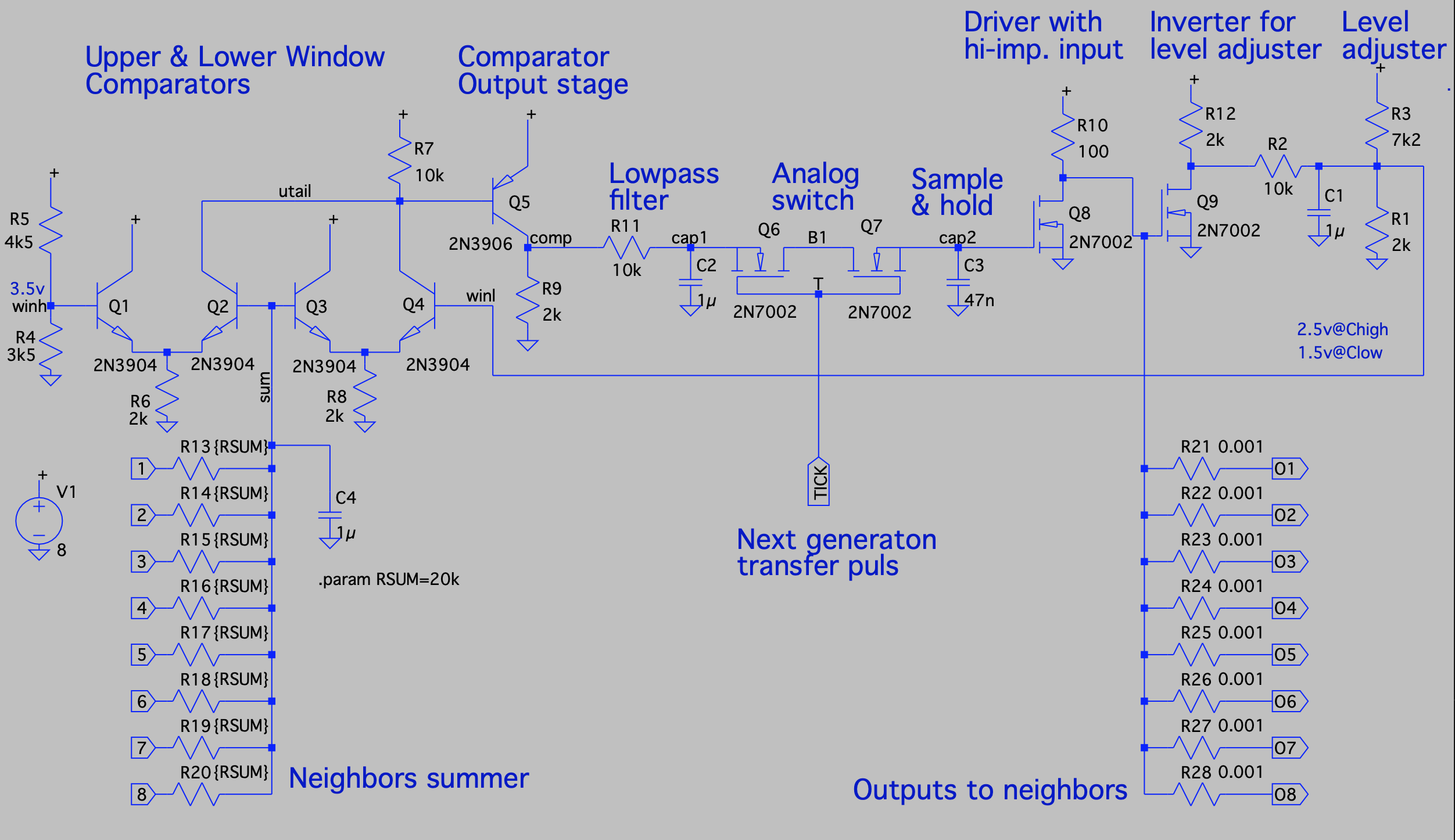
I've merged parts of the other designs into a new design using only analog components and not even having a BJT-flipflop, but rather a sample-and-hold to keep the state from just racing around the entire design uncontrollably.

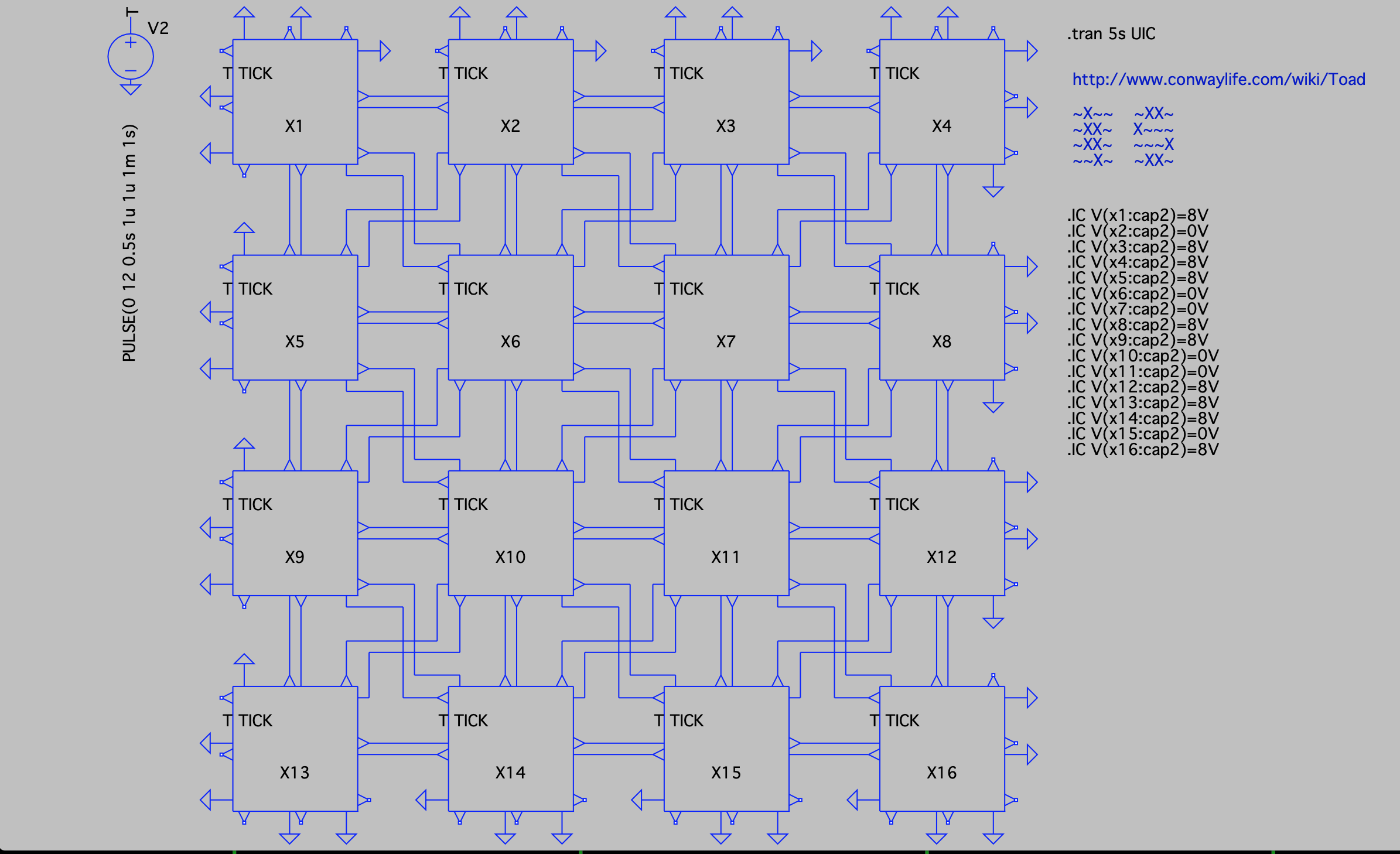
Running a simulation with a 4x4 matrix of these and adding the "Toad" pattern as the initial charges on the C3 sample&hold capacitor it runs just fine.

I'll probably make a pcbs for this and add a few dozen of them to my next pcb order and see if they run in real life as well.
 matseng
Discussions
Become a Hackaday.io Member
Create an account to leave a comment. Already have an account? Log In.
Nice Matseng, just a few remarks:
The output driver has R10, 100 Ohm, that will burn a lot of power. So better increase this, and also the summing resistors, and perhaps R6 and R8 in the comparators.
R12 in the inverter can be left out (but R3 and R1 must be re-calculated). Also saves a bit on power.
C1 in the inverter can be removed, its function is performed by C2.
R4 and R5 can be replaced by more common resistors 12K and 15K.
Where do you connect a LED ? Use an extra transistor ?
Are you sure? yes | no