Yannick (Gigawipf)
-
Update on FFB
06/09/2019 at 11:37 • 0 commentsOne main goal of this project is to make a force feedback wheel kit.
Therefore usb HID gamepad and PID must be supported.
Also a braking resistor to dissipate any generated power for quick movements was added with an anti backfeed circuit.Reports are sent at 1khz which makes for a very smooth steering experience. (Torque resolution still only 7 bits which makes ffb a bit less smooth...)
Implementing a basic HID gamepad is relatively easy, making it FFB capable a whole other story.
At least with the ST HAL library it is for example not possible to even send HID feature get requests.
This had to be patched in and the whole HID descriptor with PID is in the kilobyte range.After many days of studying the 20 year old specification and sparse examples about PID basic FFB is now supported.
Strangely some programs and games seem to not send the "Actuators Enable" command after sending a reset but instead a stop. But some do send a more sensible "stop, reset, start" sequence.
Well... thats a story for another time.The main part of the current log is that most games use constant force, friction and spring effects and these are currently implemented in a simple way and work for assetto corsa for example nicely.
The motor driver of the current prototype is still the powerstep01 but sadly two of them burned out after locking up. SPI commands can not be sent too quickly and the current resolution is limited to 7 bits. This might be fine in a slow robotic arm but not that great for FFB and any quicker applications that require precise torque.
Therefore the plan is to use a more capable motor drive solution. This will get more expensive but opens up some possibilities like the use of 3 phase servos and steppers with the same hardware and more accurate torque control and better heat dissipation when using external power mosfets.Here is a short video demo with a FFB test and a scene of me trying to drift in assetto corsa without a shifter:
Additional analog axes and buttons can be added via the inputs. Up to 16 buttons and 6 additional analog inputs are present for shifters, pedals and other controls. Maybe even add a thrustmaster wheel with SPI buttons to the free SPI port?
Compared to the Thrustmaster TX this has of course still lower torque resolution and fewer base effects, but feels much sharper and very strong if you turn up the power. I would say it comes close and should be able to surpass the consumer wheels later maybe even for a lower price.
Next Steps: persistent user configuration, code cleanup, new motor driver.
-
Choice of processor and control
04/17/2019 at 13:17 • 0 commentsOf course we need some way to send data and control signals to the OHSC for setup and direct control of important parameters.
A good option would be a serial port. This would make it usable in programs and in a terminal for human users.
It already has a hardware uart interface planned that could always be used to control everything important. But this needs a uart interface so in normal operation it would be nice to just use one usb port.
As it is planned that the device can also be used as a HID gamepad for FFB we need some way to control it when HID is active. One option would be to use a hardware uart for that or HID feature reports that would make it impossible for a human user to control without a pc application.
The best option would be to have hardware uart pins open and in hid mode setup a composite usb device with HID and CDC com port at the same time and if you don' need HID it just enables the CDC part.
This is pretty hard to do with STs HAL libraries but should be the most compatible and usable option.
So this is what i tried to setup and kind of succeeded until i found the reason why it would never transmit via CDC or break the HID part depending on the used endpoints.
It turns out that the F4 only has 4 usb endpoints and HID needs two, CDC needs two or 3 with CMD and then there is EP0... So i need at least 5 endpoints.
I could have spotted this by reading the datasheet more carefully which advertises "4 bidirectional usb endpoints". I thought that meant 4 IN and 4 OUT each but that is ~~not~~ the case. *it is. i had the buffers set incorrectly.*Now there are some options for the next iteration:
- Stay with F4 (Limited endpoints but should still work)
- Hardware uart interface and have 2 usb ports and F4
- STM32F103RC without HW float (not really needed but nice to have)
- STM32F7 (much more expensive, way faster and generally overkill)
- STM32F2? Still a cortex M3 like the F1 but a bit more capable in terms of usb and speed.
At the moment i would probably try the slower and cheaper F1 to stay in budget and keep the board small as there are some more modifications needed for the next iteration like braking resistors and anti backfeed.
The pinouts are compatible and only the usb resistors would have to be changed to switch to an F7 or stay with the F4. Everything else is software configuration.
The F1 would cost around 4.50€ in single quantities and very easy to get, the F4 almost the same with 5€ and the F7 would be about 8€ and make the device a bit more expensive.
The F411 has a usable clock speed of 96MHz and the F1 only 72MHz but that is still more than enough. The F7 clocks at over 200MHz and is pretty overkill for the rather slow usage as most of the time is already spent waiting on spi and usb and the encoder is managed by a HW timer.
I chose the F103RC for the second version because of the usb features and low price.
This allows for a more versatile and user friendly configuration. Hardware float is not strictly needed because most if not all calculations can be done in fixpoint.
The second version still retained the possibility for both F1 and F4 but was built with the F1.
The F1 also has separate ADCs which could provide some separation for voltage measurement and analog inputs for gamepad axes and control signals.
The next version will feature separate control and motor driver boards. And i might get back to the F411 as it seems like the endpoints would be sufficient and it costs the same as the F103. -
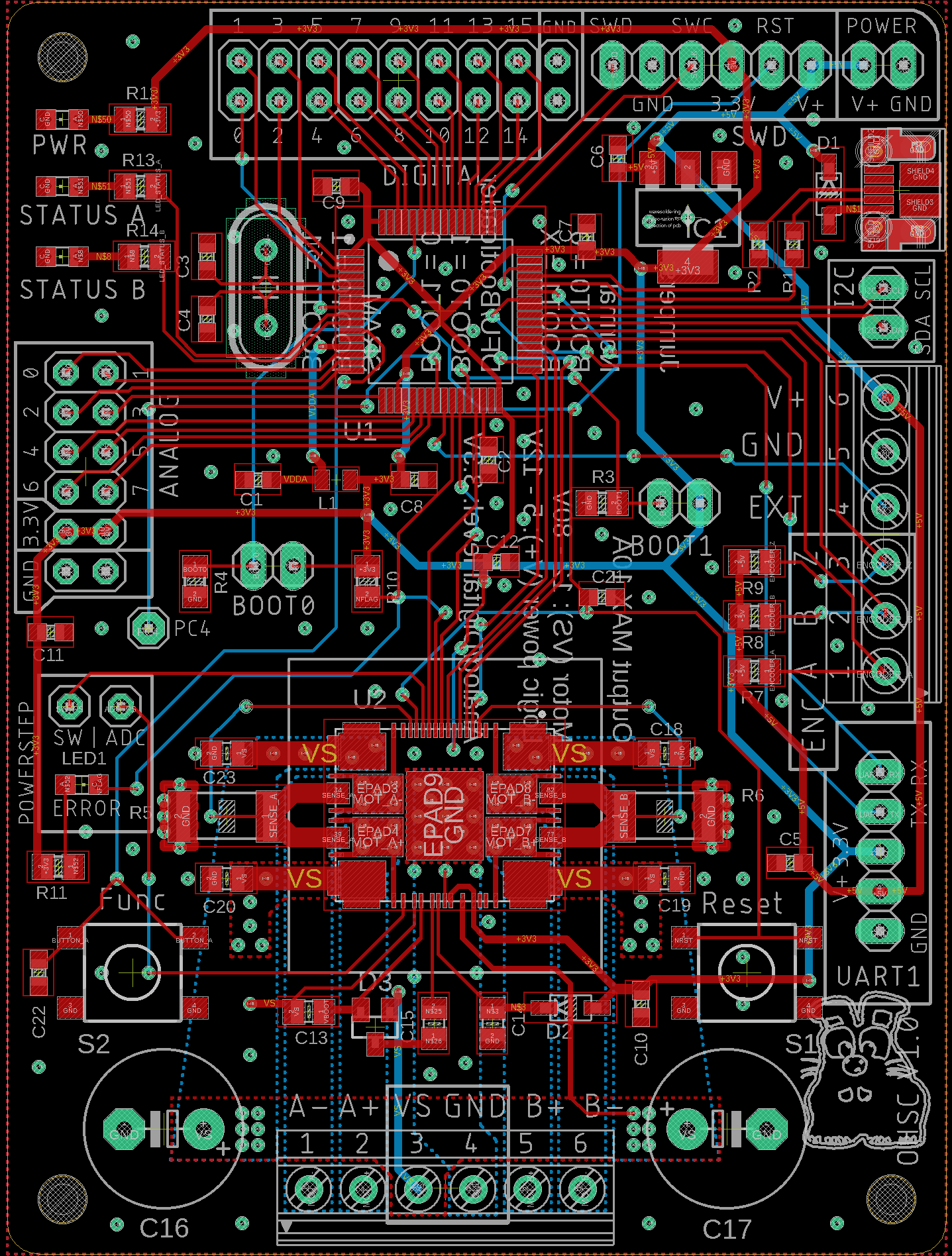
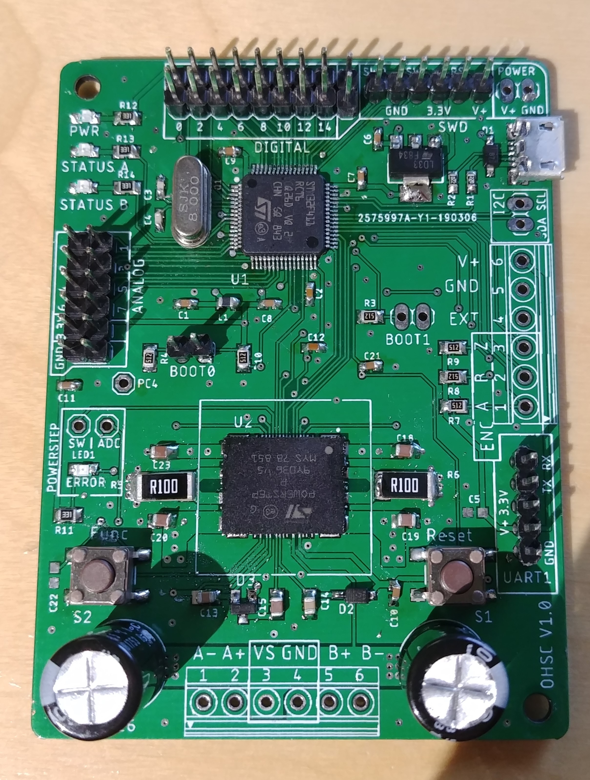
First PCB tested
03/28/2019 at 19:32 • 3 commentsFinally the first pcb arrived and is tested to find any errors in the design and see if there are any major issues.
Soldering everything by hand takes some patience but everything works as it should.
A few problems spotted in the first design:
1. Vias under the current shunts are too close to the pads and can be bridged to the resistor while soldering and short out the shunt voltage.
2. Pullups of encoder were connected to 5v instead of 3.3v. Easy to bodge for now and fixed in the next version.
3. 3.5mm terminals might be too small for big motor wires. Maybe add a 5mm footprint and move the caps and buttons.
4. USB footprint from eagle not exactly the correct one for the ports. Drilled holes are in slightly different spots.
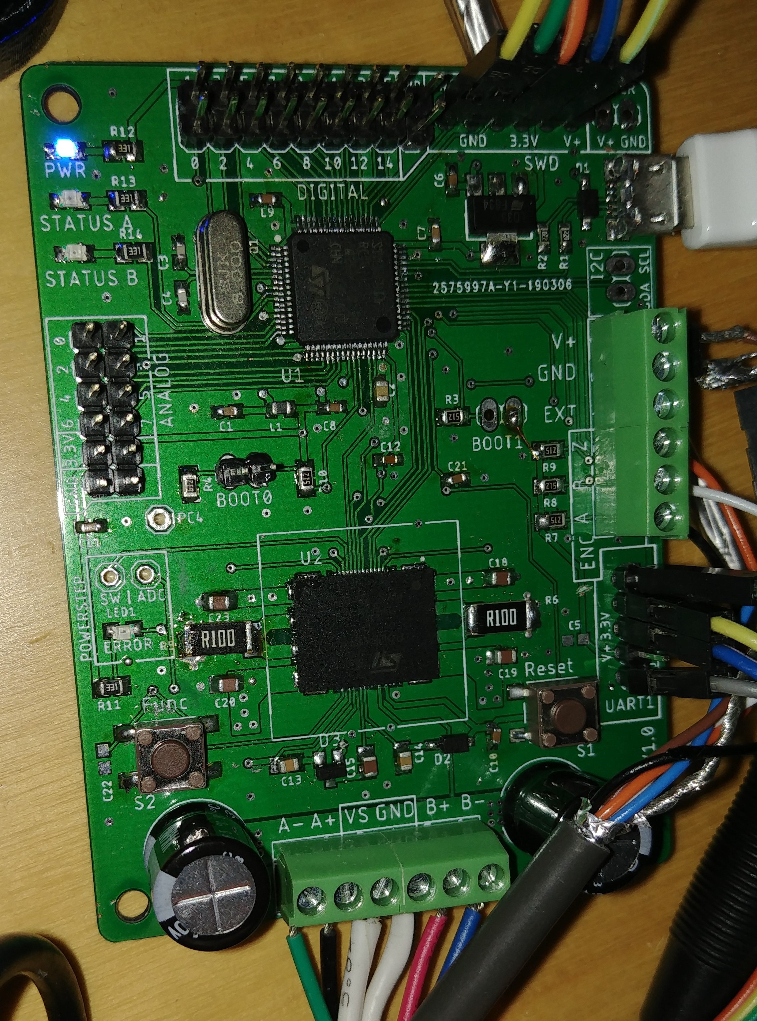
Strange as the part numbers were identical and can be fixed by bending the mounting pins of the port inwards but should be changed to the correct one.Apart from that the driver and processor work correctly. I chose the STM32F411 as the main processor running at 96MHz. 2 LEDs for status messages, one power led and one direct driver flag led for critical errors are present on the board.
![]() And of course the gamepad communication is working with 16 buttons and 8 analog inputs.
And of course the gamepad communication is working with 16 buttons and 8 analog inputs.
The encoder input is correctly scaled to 1080° of rotation and perfectly matches the virtual wheel in project cars. -
Designing a pcb prototype
03/05/2019 at 16:28 • 0 commentsWhile the current prototype shows promising results it is a mess of wires and many pins on the stm are already blocked by the discovery board. Other boards where the powerstep shield can be stacked onto often have no usb port or other issues.
I spent quite a few days researching parts, designing a pcb and preparing the cubemx project for the new layout and chip.
For the next prototype i chose the stm32f411RCT6. This processor has enough pins for 8 analog and 16 digital pins directly connected to the chip while still having usb, uart, internal spi for the powerstep and screw terminals for the encoder.
Some space is available to allow for a larger heatsink if needed. In theory it should be able to handle 80V but in current mode the driver runs best at 12-20V and this is probably what most users will have available anyways. At higher voltages the driver get really hot. In voltage mode not that much but i find the torque reaction to be much smoother and quicker in current mode.
Now i will wait for all the parts to arrive and hope that nothing blows up in the first test.
![]()
One other thing still missing is a nice nema34 dual shaft motor. The 34HS59-5004D from stepperonline looks like a perfect match with pre cut keyway and smaller back shaft and mounting holes for the encoder. Sadly it is not available at the moment so i will need to wait more or find a different one.
After a week my parts finally showed up except for the terminal blocks.
Not the most pretty soldering but it was all hand soldered and that lqfp powerstep is a beast to hand solder. Cleanup will be done once the terminal blocks are here.![]()
-
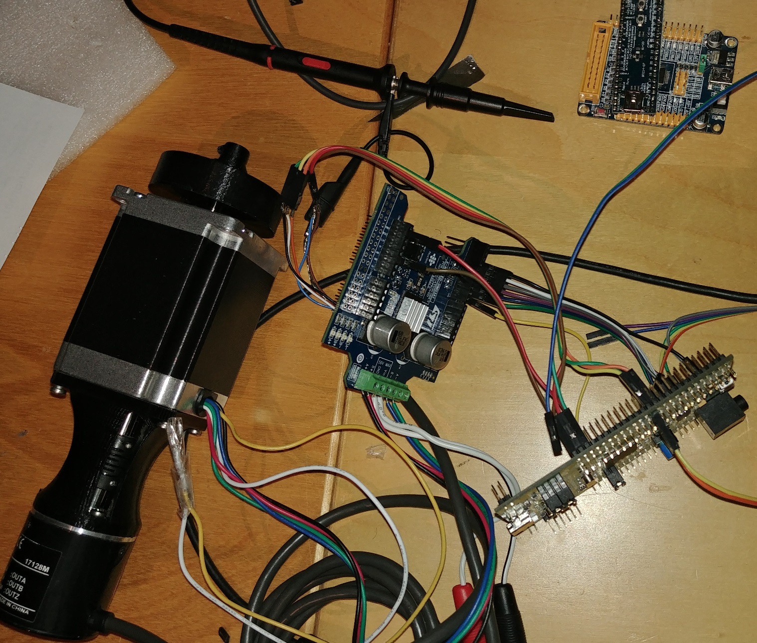
Prototyping and FOC
02/15/2019 at 19:47 • 0 commentsMy prototype consists of a stm32f4 discovery board and a powerstep01 shield.
The goal of this stage is to implement a stable FOC control loop using this standard stepper driver. I chose this driver because it allows for up to 10A of current in current and sine voltage mode and can be controlled via spi quickly and stepped in stepclock mode.The field oriented control like approach works by keeping track of the step positions and aligning bursts of microsteps less than one electrical rotation to the current position and making sure the stepper never skips a full step.
This needs a high resolution encoder with sub microstep resolution. I chose a 10k count E6B2CWZ6C (clone) encoder for this prototype.
Microstepping is set to 1/16 because this is the highest setting the driver supports in both current and voltage mode and current mode allows for higher holding power between steps.Perfect alignment of the shafts is crucial for smooth stepping so a sturdy adapter was printed.
Yes it is messy but there is no other option to get the driver connected to this board. The end result will feature a custom pcb :)
![]()
The FOC loop is pretty much working right now and can turn heavy loads at stall conditions without cogging and the feeling of skipped steps.
![]()
This video was made with <0.4A of current and a Nema 24 motor. Imagine a Nema 36 or 42 at up to 10A.
The feeling is smooth as butter when forcing the load away. Very unlike an open loop stepper.At the moment the position holding is done using a PID loop which has to be tuned for the specific load and torque profile needed. This creates some overshoot which has to be reduced for accurate applications. Of course in this video the overshoot is extremely exaggerated because of the heavy load but even with small loads about 1-5 microsteps of overshoot and offset can be observed when the loop is reasonably tuned but not perfect.
Later a step/dir interface to use this closed loop controller as a replacement for open loop stepper drivers will be implemented and this will need at least near microstep accuracy to be usable but the main goal is to provide smooth torque at stalls for applications that would traditionally need servo motors like linear actuators, force feedback and robots.
Open FFBoard
A modular and open source force feedback interface and motor driver for DIY wheels and controllers
 And of course the gamepad communication is working with 16 buttons and 8 analog inputs.