It feels like that a project is never quite finished, that there's always improvements that can be made. I never knew that was appeared to be a rather simple project could get so deep.
Trying another transistor
I was never satisfied about the fact that I was unable to get the remote to work effectively with a 1 percent duty cycle with the mosfet. So what did I do? I decided to try another transistor, this time a darlington pair, model FMMT634TA. It's rated for up to 900 mA continuous with a peak pulse rating of 5 amps. Being a darlingon pair, the base-emitter voltage drop is a bit higher, as there's essentially two diodes in series, but by doing some quick math, I found that would be no problem as only a small around of drive current is needed thanks to it's very high gain ( 5 mA of drive current is more than enough to drive the transistor fully saturated at it max current rating.) I found a 140 ohm resistor in my box to fit the bill for use with 2xAA nimh cells (fully charged with a measured voltage of around 2.76 volts with the 140 ohm resistor provides around 8 mA of drive current and at a more discharged voltage of 2.4 volts, should still provide a drive current of around 5 mA.)
A new achievement
I then went off and assembled (yet another) board using the new transistor. In hopes of trying to drive the IR LED close to 900 mA (with the batteries fully charged) I selected the lowest value resistor that I had in my box to be in series with the IR LED, 680 milliohms.
I then went to test it out on that pesky TV that I've had a hard time turning off in the past. I tried that super narrow beam IR LED in the past. Didn't work fantastic. I then swapped out the LED for an LED with a more normal 20 degree angle. Consistent success! I was able to turn it off, even at the opposite end of the room consistently. A moment of achievement.
An oscilliscope
Thanks to being in a review program, I finally managed to get my hands on an oscilliscope that's not a complete toy. It's a Hantek tablet oscilloscope, model T01112. It's by no means a professional scope. It's rather quirky in nature and has a number of irritating bugs. It's rated at 110 MHz with 250 MSa/S (sample rate halves when both channels are turned on.)
Some interesting results
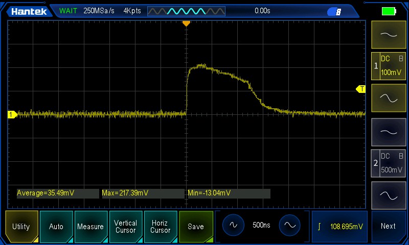
I first wanted to know, how much current was running though the LED. With a 1 percent duty cycle at 38 KHz, give a pulse width of around ,263 microseconds, I don't know of any multimeter that could actually measure such a short duration pulse, which is why I needed a scope to measure. I measured the current by measuring the voltage of the resistor in series with the IR LED. As seen in the screenshot below, the measured duration is a bit longer than .263 microscends for some reason. This may be due to the turn on/turn off times of the transistor, which in the datasheet shows 290 ns for turn on and 2400 ns for turn off as typical values. Those figures seem to be somewhat roughly what I got.
I also came to the realization while writing this piece that even though I'm driving the transistor with a 1 percent duty cycle, the IR LED is staying on for a bit longer (around a 5 percent duty cycle) thanks to the transistor not turning off fast enough, which isn't great if using an LED only rated at a 1 percent duty cycle.
As for the amount of current driven though the IR LED, with a peak reading of around .217 volts over a .68 ohm resistor, that comes out to around 319 mA. You have to take that as a ballpark figure due to the fact that my scope's reading isn't super accurate and the resistor in use has a 5 percent tolerance. The 319 mA is a bit lower than my back of the envelope math which came out to around 647 mA ((2.76-1.5-.82)/.68) for an 5IRC-940 LED (model is no longer produced) with a measured fully charged battery voltage of around 2.76 volts.
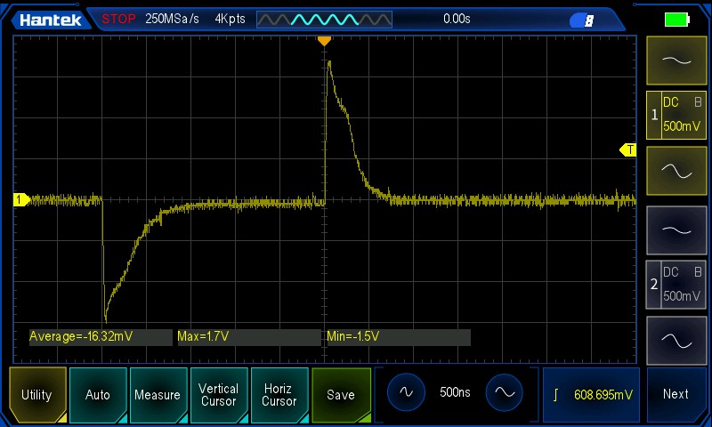
Why the rather large discrepancy? Was I doing an outright terrible job at using my scope or was the my scope itself? As a sanity check, I measured the voltage across the 140 ohm resistor used for driving the base of the transistor. Quick math indicated drive current should be around 7.9 mA assuming worse case voltage drop across the base emitter and the voltage of the batteries ((2.76-1.65)/140). I was initially surprised by the waveform I got on the scope, getting both a positive and negative portion, until I realized that it's the result of current flowing one direction to turn the transistor on and then flowing the opposite direction when the transistor is turned off. I do find it strange that it's not quite symmetrical in terms of amplitude. The negative portion of the pulse in this case is when the transistor is being turned on (was easier to probe in my case with the leads reversed.) Got a measured current of around 7.4 mA which is in the ballpark of what I expected. Also, the width of the pulse is fairly consistent with what's supposed to be a 1 percent duty cycle signal at 38 KHz.

Now it was time to find out what was limiting the current. I turned towards measuring the forward voltage of the LED with the scope.
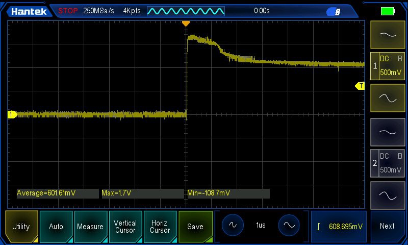
I got a peak forward voltage rating of around 1.7 volts. Doing the math based on that figure gives us around 353 mA (2.76-1.7-.82)/.68), close to what was measured. The majority of the remaining discrepancy is likely due to the actual voltage drop across the transistor differing from the value that I plugged into from the datasheet.
Why did I get a higher forward voltage than the specified max forward voltage drop for the 5IRC-940 LED in the datasheet? Turns out that value is quoted at forward current at 50 mA, and provides no value at it's maxed pulsed current. I looked at another IR LED, model IR204-A-L, and its datasheet actually provides the typical forward voltage value of 2.6 volts at a peak pulsed current of one amp. For many LEDs that can be puled with a current of an amp or more, their datasheets don't provide the forward voltage value. As demonstrated, that missing information can throw off envelop calculations significantly, making it hard to optimize driving the IR LED.
As for why the IR LED forward voltage stays elevated for some a long time, perhaps it's due to some leakage current occurring while sending a pulse stream. Perhaps someone more learned than me can comment.
I also took the opportunity to check the gate current of one of the remotes using the mosfet. As expected, you can see it takes some time to charge/discharge the gate capacitor thanks to the limited current (of around 11 mA with a 140 ohm resistor), which is why it worked so poorly with a 1 percent duty cycle (screenshot below is with a 10 percent duty cycle.)
Key takeaways:
Just because a transistor is being driven at a particular duty cycle doesn't guarantee the output will match. The Darlington pair transistor did improve things significantly, but a key drawback is that it takes a fairly long time to turn off, resulting in a significantly higher duty cycle than indented, which can be problematic for some IR LEDs long term. The forward voltage of IR LEDs tend to be a bit higher when driven a high pulse currents. Thanks to many datasheets of IR LEDs not providing forward voltage values when driven at their max peak pulse current, it's hard optimize circuits for max current without hooking up a scope and seeing what's going on.
Moving forward
I want to give the mosfet another shot as it has a very fast turn on/off time. I'm planning on using a lower value gate resistor and see if I can reduce the charge/discharge time a bit to make feasable to drive an IR LED with a 1 percent duty cycle.
Discussions
Become a Hackaday.io Member
Create an account to leave a comment. Already have an account? Log In.