March 9, 2019
First builds are always fun. It's where you find out where the mistakes are.
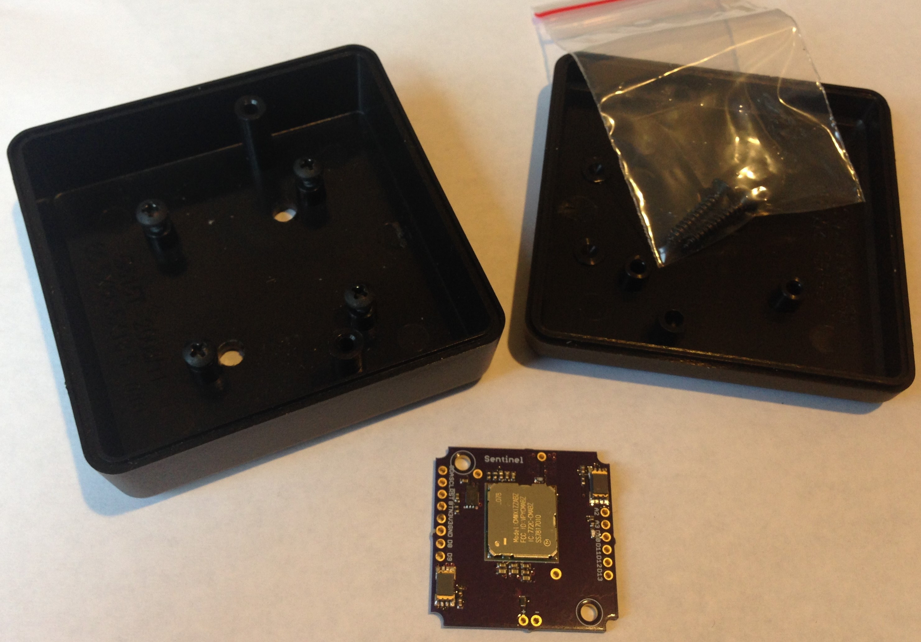
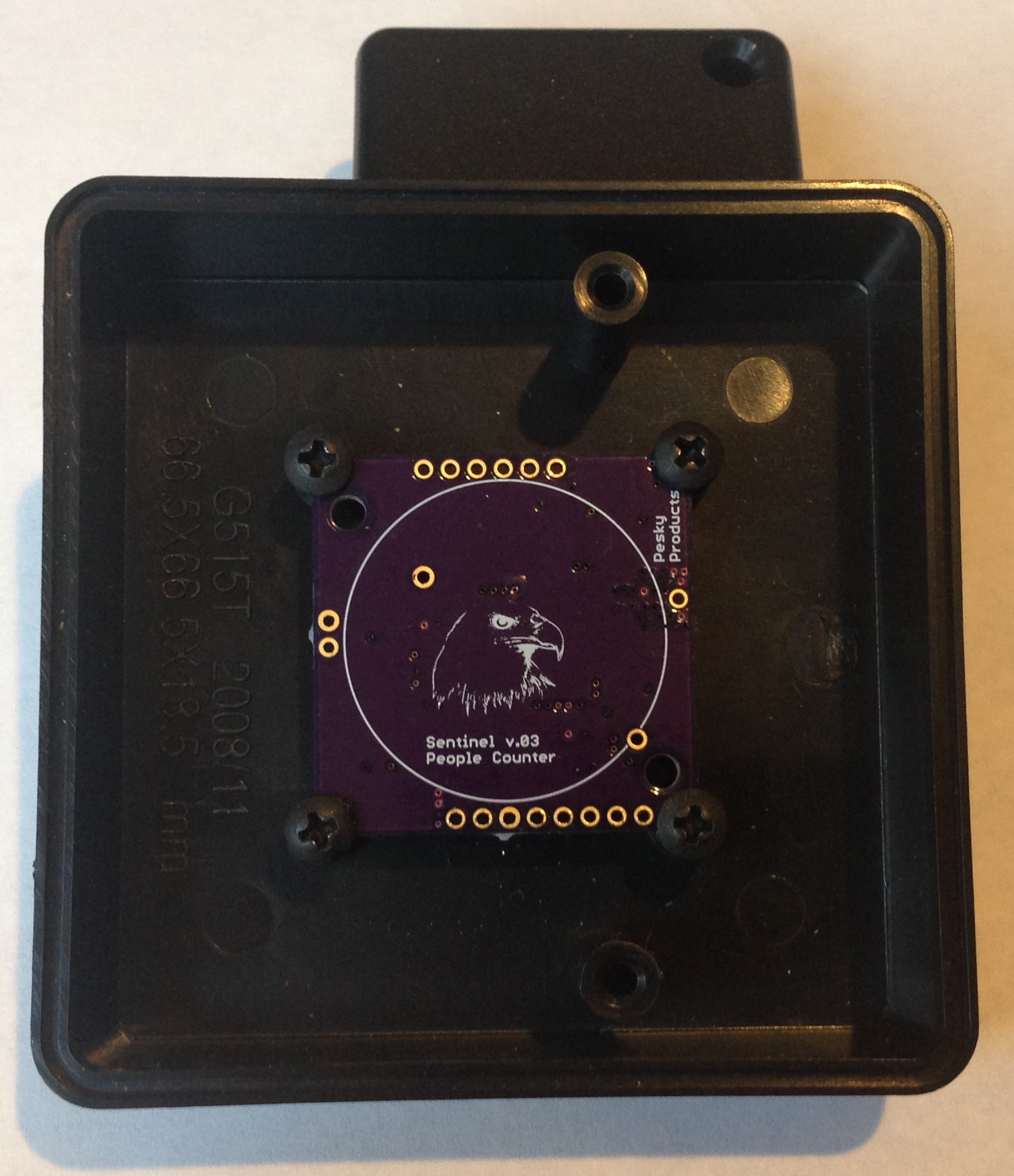
I received my first iteration of the People Counter pcbs from OSH Park and immediately tried the fit into the two low-cost containers I plan to use for this project. One is the Bud Industries HP-3649-B costing $1.30 each per 100, and the other is the Hammond 1551-HBK costing $1.61 each per 100. Fit into the Bud box was as expected since I had tested this on other projects and hadn't modified the design of the mounting devices (quarter circles) on the pcb. I did however change the position of the holes for mounting into the Hammond box without realizing that they are asymmetrically placed with respect to the pcb edges. So the People Counter fits fine on the Hammond box mounting posts if I install it upside down! I redesigned the board for proper hole placement, having to move some edge pin ports around to do so, and resubmitted to OSH Park. In the meantime I will use the Bud box for testing and optimizing function.

The Bud box is roomy and affords space for 2 AA batteries and holder.

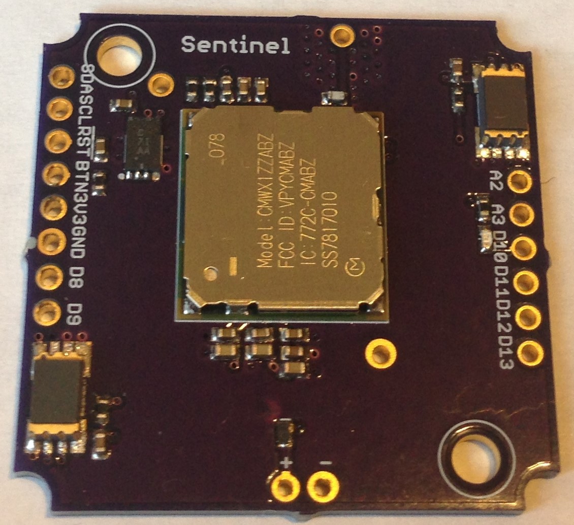
It took me about an hour to assemble the relatively simple board. Here is what the assembled pcb looks like:
 Programming is through the SWD port on pins D8 and D9 using an ST-Link V2 I bought from e-bay. I used the "ST Link (STM32L0)" programmer selected from the tools menu in the Arduino IDE and the "Upload Using Programmer" method in the Sketch pull down menu. On this device, I need to use a jumper to pull the Boot pin (BTN, which is also a user button on D2) HIGH to put the STM32L082 in boot mode to allow programming. Not as convenient as using on-board buttons and USB connectors but it worked well enough.
Serial output for debugging was available via Serial 2 on pins A2/A3. I have a blue led on pin D10 (shared with SPI nCS) for indication as well which helped make sure things were happening in the sketch as they should.
I am using the Murata CMWX1ZZABZ (STM32L082 + SX1276) as host MCU and for LoRaWAN connectivity. LoRaWAN is ideal for low data rates and infrequent messages. This application needs to send just a few bytes every so often (1 or 10 minutes intervals, for example) to the LoRaWAN gateway ("I got three ingress counts and 6 ingress counts since the last update!"). It could also send a LoRaWAN Tx message every time it detects an ingress or egress event. I am not sure this would work well in a situation where a LoRaWAN Tx message had to be sent every time someone entered a big conference room as it filled up for a meeting. My preference would be to update the egress and ingress counts on a periodic basis, like once a minute, but only if there was a change since the last update, and otherwise every 10 or 30 minutes. The Tx strategy will depend on the use case and the customers' preference.
The two Calipile (TPiS 1S 1385) thermopile sensors are placed as far from each other on the pcb as I could manage. The diagonal placement also insures the orientation of the box doesn't matter except to properly identify which direction is egress and which is ingress, but this is arbitrary. Might as well be directions 1 and 2. The Calipile's have address pins to allow up to four on a single I2C bus. These are set to respond to I2C addresses 0x0C and 0x0D. These have dedicated interrupts as well which ensures the temperature threshold crossing events are properly attributed to the corresponding sensor.
There is a PTH for soldering an 82-mm copper wire as a LoRaWAN monopole antenna. Later designs use a chip/pcb antenna. There are two PTHs for mounting the 3V, 950 mAH CR2477NAH I plan to use when deployed. Finally, there is a secure element ATECC608A to allow secure boot, secure LoRaWAN provisioning and key storage, as well as secure FOTA when these are deployed in the "field" (office building, hospital, factory, etc.). Security is often neglected in IoT devices and it is not straightforward to get it right. I will discuss all of these aspects in later logs but here I want to start discussing performance and power usage.
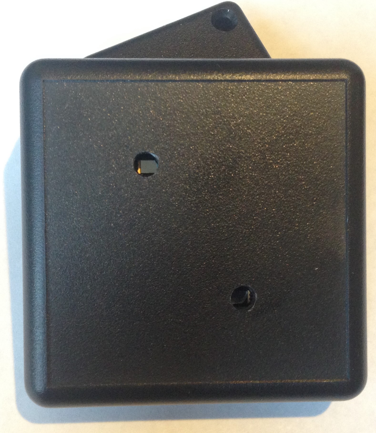
The Calipile sensors have a 120 degree field of view that needs to be stopped down a bit to increase the discrimination, both in terms of increasing the effective separation distance of the sensors but also by narrowing the contribution to the signal from background. I started with 3-mm-diameter holes I drilled into the Bud box. At ~6 mm from the Calipile sensor faces to the holes this amounts to a reduced field of view of ~28 degrees. I had a hard time measuring anything. This could have been due to problems I was having with the firmware or interrupts since I was doing several things at once. But for whatever reason I decided to increase the hole diameter to ~4 mm and this seemed to work robustly. I need to find a method for drilling these holes with more precision; they are not centered on the sensors which means the sensitivity will depend on mounting direction which is not what I intended.

This produces a field of view of ~37 degrees. I was able to detect ingress and egress events (left-to-right hand swipes vs. right-to-left ones) with high accuracy from about 15 cm away from the box face. I am sure there is a trade off between hole diameter, object speed, and detection distance. I haven't optimized the design by any means but I am gratified that I can detect events with high accuracy from a useable distance with these modest holes in the box. I would like to avoid the more elaborate lensing or tube approach discussed in the CaliPile Application Software Evaluation Guide if possible.
One of the main goals of this project is remote, battery-powered people counting. If I had the luxury of connecting to main power wherever this device might be placed the design would be very different. So the main concern after people counting accuracy and reliability is average power usage. And since this device will spend most of its time waiting for something to happen, it has to have a very low sleep current. So the first thing I did was measure the power usage running a typical program without the LoRaWAN element. I know from other projects that at a 10 minute duty cycle LoRaWAN Tx costs about 20 uA.
I used ST's X-Nucleo-LPM01 power meter set at 3 V (nominal coin cell battery output). I could see the power rise everytime I waved my hand over the device. I was seeing about 25 uA when the device was in STOP mode with ~1.5 sec excursions to ~900 uA when the interrupts fired and I2C transactions took place. One thing I noticed right away is that for a while the device would work as expected and then all of a sudden the current would jump to ~300 uA and just stay there until another gesture was detected. It took me a while to understand that this happens when only one of the interrupts fires so the correlation condition fails, leaving one interrupt active until the next true event is detected. This can happen, for example, when someone approaches the device but only close enough to set off one of the threshold detectors. I had to fix this in software (it's always the software !) by getting the logic right. In this case, I simply clear any interrupt in the main loop after it is detected because the really useful information is the interrupt time which is captured in the interrupt handler. More power tests once the LoRaWAN Tx is active will be required but for now it seems the Calipile thermopile sensor data sheet is accurate in that each sensor uses < 15 uA while fully active; I make it ~11 uA or so. The total I measured, ~25 uA, plus the typical ~20 uA for LoRaWAN Tx at a 10 minute duty cycle would bring the total People Counter average power usage somewhere in the neighborhood of ~50 uA. With the 950 mAH coin cell battery then, the battery lifetime of such a People Counter device would be ~2 years depending on the number of people the device is expected to count.
So far in the project I have encountered no show stoppers and it looks like I might end up with a really useful device! Next log, I will add LoRaWAN Tx and see what kind of accuracy I might be able to get in a real test of the functionality...
 Kris Winer
Discussions
Become a Hackaday.io Member
Create an account to leave a comment. Already have an account? Log In.